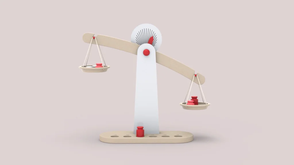

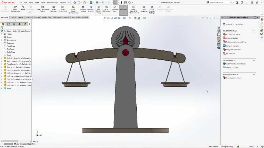
In this tutorial I wanted to play around with a range of features and tools to create a set of toy balance scales. Within the tutorial I cover a range of things from creating an assembly with several mate types, creating a set of scale weights using configurations, editing the appearance of the weight using linked display states and finally adding the mates to the finished assembly to create a motion analysis. Before following this tutorial, please download the part files here. To create all the parts for this assembly is used the multi body part way of modelling the scales. I always find this method easier to use, especially when I want to create parts that fit or move together. For the assembly, several standard mate types were used, including coincident, tangent, and concentric, this also includes using the concentric mate with locked rotation.
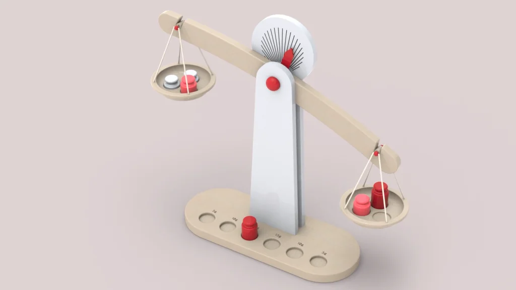
Once the balance scales parts are assembled, I could move onto the set of scale weights. These were created using a single part and configurations, I used configurations for this as I wanted several weights with the exact same profile but with a single altered height dimension which would determine the mass of each weight. A beech material was applied to the model, and I pre-calculated the height of each weight to make a 5,10 and 15 gram set with this material. This was done pre-tutorial and was worked out by trial and error. I would alter the height bit by bit until I reached the desired weights within two decimal points of the mass units. Once I had the heights, I started with the 15 gram weight, and sketched out the profile, leaving the height dimension as the fully defining sketch element. I then renamed the default configuration as 15 grams and tested out the weight using the evaluate tab and mass properties.
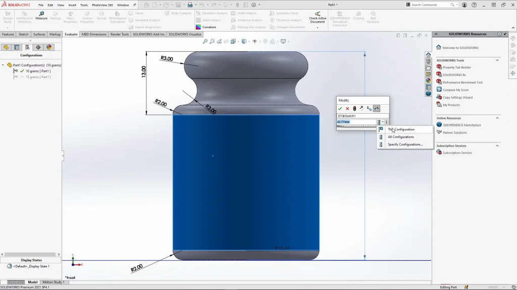
From here, I could continue by adding a new configuration, and naming it 10 grams. I altered the height dimension but dropped down the configuration options now available within the sketch and selected ‘This Configuration’. This would ensure that the dimension changes would only apply to the configuration that I was selected. The process was repeated for the 5 gram weight.
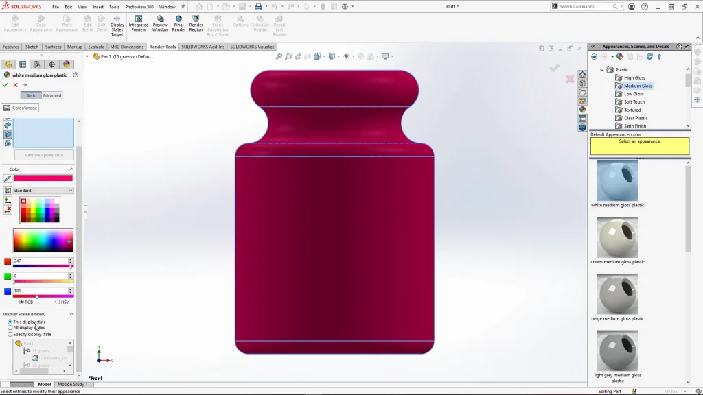
As mentioned earlier I applied the beech material, but before applying, under the appearance tab, I unchecked ‘apply appearance of’, this removes the beech appearance from the part. I wanted to add different appearances to my weights set but have each one be a different color. To do this, you need to go to the display states within its properties and check ‘link display states to configurations’. Before applying an appearance, you need to look at the display state options, ensure that you can see ‘linked’ in brackets next to it. For this part I could keep the selection on ‘This Configuration’ but if you were to want the appearance to be applied to specific configurations, you can select ‘Specify Display State’. Once I am happy with my selections, I could apply the appearance. Again, I repeated this for all three weights.
With all the mates applied, and the weights inserted into the assembly, the scales could be tested before creating the motion study. Any parts that would not need to move or that should remain in place during the motion study were fixed within the assembly. This includes the front and back panels attached to the already fixed base part and the pin. This allows the scales arm part to make contact with the pin during the analysis and create some friction between the parts. This helps slow down the swing of the scales more quickly than if it was only relying on a concentric mate to move. As you will see in the tutorial, I suppress the concentric mate that holds the scales arm on the circular edge of the pin. It is important to follow the assembly mating instructions I give in the tutorial carefully and the motion study settings which includes suppressing other mates to achieve the finished analysis.
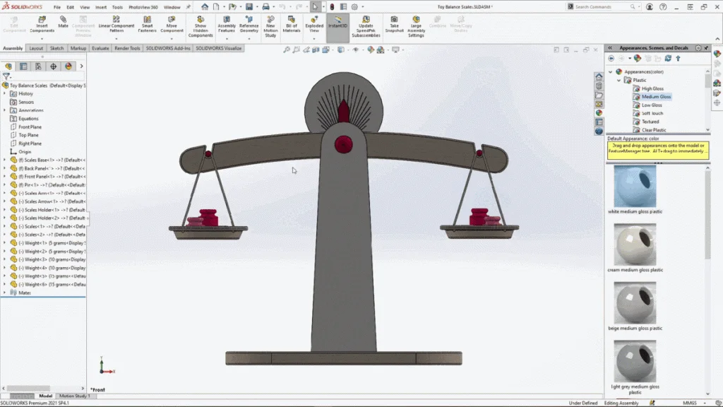
For the motion analysis I used two elements, gravity, and contacts. All the components in the assembly were selected for the contacts, this allows parts to interact with each other as they would by adding a frictional force through the component material properties, for this I kept the material on acrylic. This is a simple motion study that required very particular mates to create a set of balance scales that functioned well. Once I had the finished analysis, an animation is created, this animation could be exported it directly into SOLIDWORKS Visualize and rendered, you will see the full rendered animation at the end of the tutorial.