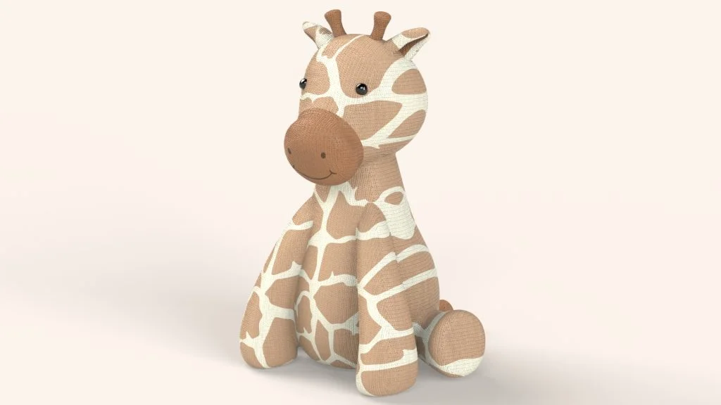

This is a 2-part 3D Sculptor tutorial to create a Giraffe teddy using only sub division shapes. Across both tutorials see how I used the cone and cylinder shapes to create this Giraffe form, and then export it into SOLIDWORKS for editing. Most of the modelling for the Giraffe is very rough and freehand in that I wasn’t too not worried about the overall scale or size of the teddy. Overall sizing could be changed in SOLIDWORKS once the whole teddy was modelled. So, as you follow the tutorial you can copy where I place a sub-division surface and then watch how I manipulate it into place. Your model does not have to be perfect, and you can always go back into each shape you create and edit it as you go along.
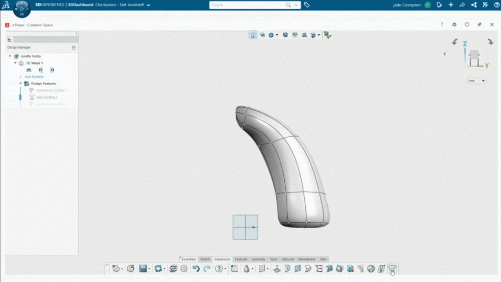
For the main Giraffe body, I chose a shape that would be easiest to manipulate into the body shape, so I chose a cone. The cone shape could be manipulated easily into the belly, bottom, and neck of the teddy. It is very easy to create organic shapes quickly with a lot of control, but I think it’s important to think ahead when choosing which sub-division shape you choose to model with as you want the shape choice to help model your desired form easier. As I go through the Giraffe model, the cone shape worked best for most features and the cylinder shape was most useful for detail parts such as the eyes and tail as you will see in part 2 of the tutorial.
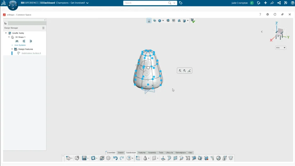
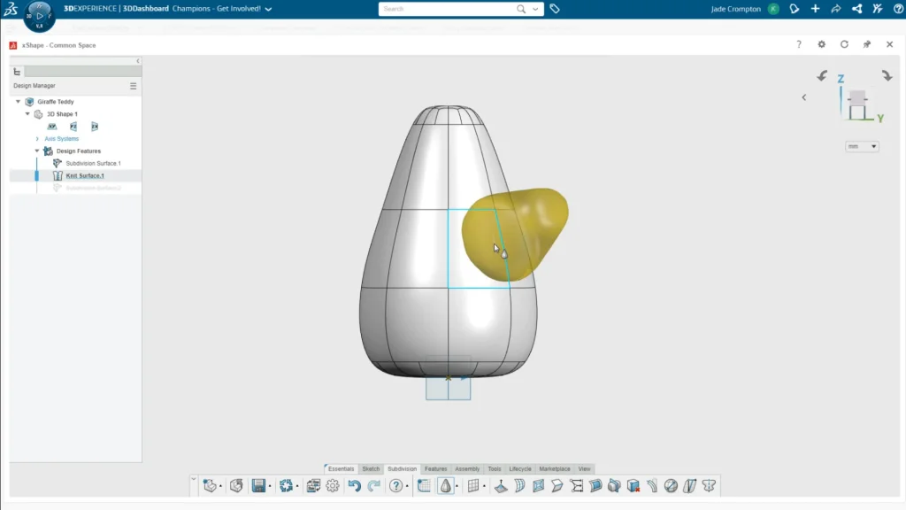
Another feature of 3D sculptor that really assists you in your modelling process is the snapping feature, when you bring in another shape you can snap the shape onto the faces of the shapes you already have in place. This stops you placing the shape into the document and it being far away from the model. It also helps speed up the modelling process without worrying about mates, planes, or the exact position of a part. You can place the new shapes anywhere with ease.
When it came to modelling the Giraffe legs, I wanted to be able to mirror over the leg to the other side of the body, but 3D Sculptor is currently missing a mirror feature. So, until this is added, you can use the symmetry tool. There is a way of using the symmetry tool and then deleting the faces in the center of a part to create two separate bodies. But in my case, it didn’t matter if the parts were still joint together as they were hidden within the Giraffe body.
To use the symmetry tool to ‘mirror’ the leg over, I had to translate some of the faces of the leg shape past the plane I wanted to mirror from. I then turned on the symmetry feature and selected the mirroring plane, this in a way ‘mirrored over’ the leg shape. Keeping the symmetry tool on, I could then edit the original shape further and the other leg would change at the same time.
When you place the shape, you have the option to scale up the shape and add or subtract control loops and faces. This is something that with practice you will be able to guess how many control loops your shape will need to create your design. You can apply these options before you start modelling the shape, or you can add them in when needed using the Insert Loops tool. I added an extra loop to the Giraffe head part as I needed more control points to create a nose for the Giraffe.
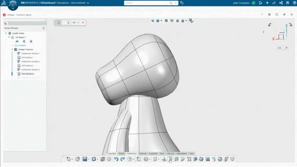
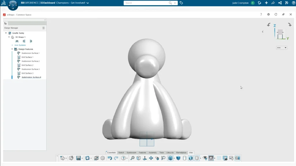
By the end of part 1 of this tutorial, you should have the main body of the Giraffe complete. As I mention in the tutorial, your model does not need to be perfect, or look exactly the same as mine. You could actually add more detail to the teddy if you wish, this design is just a good way of getting acquainted with some of the basics of modelling with sub-division surfaces.