

Hello to all,
Welcome to the new edition of the SOLIDWORKS Support Monthly News! This monthly news blog is co-authored by members of the SOLIDWORKS Technical Support teams worldwide.
Adding additional hole sizes in Toolbox Hole Wizard (Using Excel)
By Ayush Agrawal
SOLIDWORKS® Hole Wizard gives a wide range of industry-standard hole sizes. It also gives the user the ability to add custom hole sizes that are not in the default list. Not a lot of people are familiar with this functionality, so let’s see how that is done.
When you are working with a huge data set of thread sizes, an easier way is to feed the data using excel sheets. You can export Hole Wizard data with Excel files, make changes and import back the data with new sizes in the Toolbox Configuration tool.
Prerequisites and Preparations
- Keep ready the complete data set containing various thread parameters like Size, Pitch, Diameter, etc.
- Beware of what you download from the internet. Verify the data if downloaded from the internet before using it.
Let’s get going!
You’re gonna start by opening Toolbox Settings by going either to Start, All Programs, SolidWorks
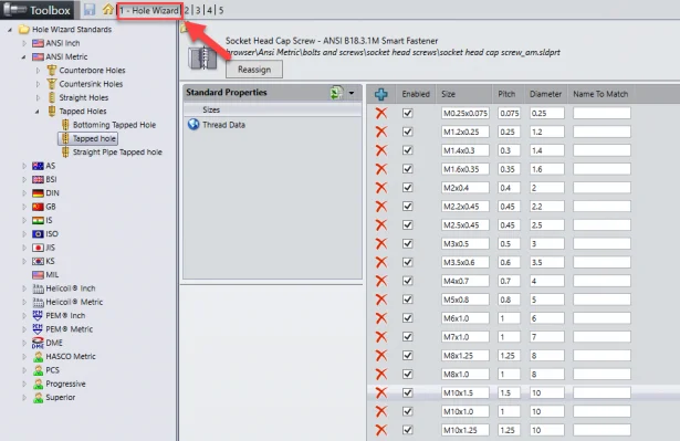
Select the ‘Configure’ button. The tab “1 – Hole Wizard” shows existing hole standards and sizes.
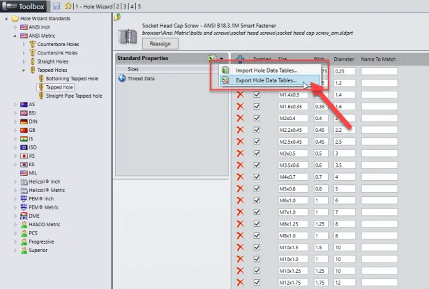
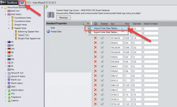
Open the Hole Standard and the hole type in which you want to add the new sizes. For now, we will take the example of ANSI Metric Tapped holes and add new sizes to them. You can export an excel file of existing sizes under the dropdown beside the small excel icon, as shown in the below image. We will use this excel as it comes with a proper format and setup of existing sizes.
Note: Keep a backup of the original excel file before making changes to avoid unseen errors.
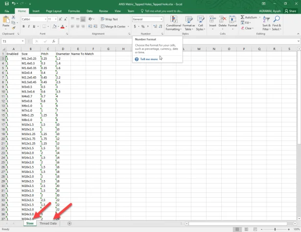
The exported Excel file typically has 3 tabs, corresponding to the Standard Properties of each Hole Wizard type:
- Sizes
- Thread Data (except for Straight Holes)
- Screw Clearances (except for Tapped Holes)
Our ANSI Metric Tapped holes excel looks like this:
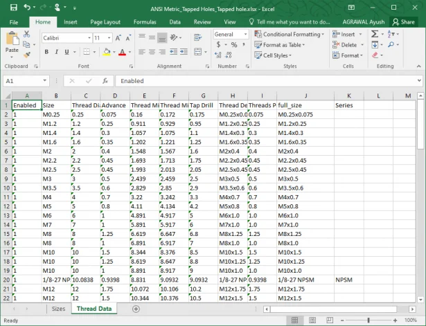
To add new sizes, add rows and fill the data in all columns in all the tabs.
Things to remember:
- In the ‘Thread Data’ tab, the catch here is that the “full_size” field must match what was entered in “Size” field in the Sizes tab. i.e Size = full_size = Thread Description
- Pitch = Advance = Threads Per Unit
- Make sure to follow all the original formatting of the excel.
Once all the changes are done, save the excel sheet. Now Import the edited excel sheet and you can find the additional hole sizes populate in the database.
Make sure you save the Toolbox changes.
Now you can find the new sizes in the Hole Wizard to add to your SOLIDWORKS model.
The same process has to be followed for every hole type.
Also refer this previous blog post that shows another approach for adding new sizes, useful when working with small dataset or just a few new sizes:
Happy Designing !!
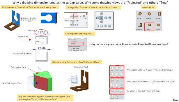
Why does a drawing dimension creates a wrong value. Why are some drawing views “Projected” and others “True”?
By Mario Iocco
How Composer works in background while exporting animations to video outputs?
By Rohit Chavan
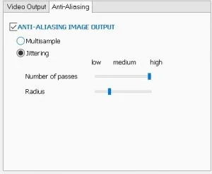
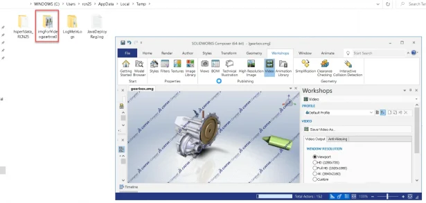
We all are aware that SOLIDWORKS® Composer™ has the ability to export the animations created in .smg files to various video output formats like AVI, MP4, MKV and FLV. Apart from it, Composer™ also has various options to customize your video output as per requirements available under Workshops > Video. You may also refer topic ‘Video Workshop’ under Composer User’s guide > Working in Workshops, in Composer help document. .
After applying all the desired settings, clicking ‘Save video as’, browse to desired location and save the video, while the process is running we can notice the status of the progress of video creation in Status bar of Composer.
But what exactly is the background process in creating a video is mentioned below –
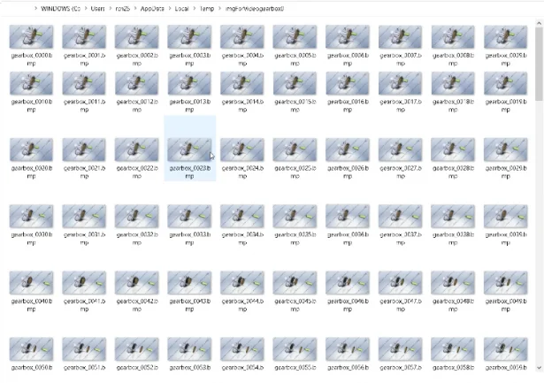
While creating the video, initially the images for video are created in folder named ‘imgForVideo
Composer™ initially calculates total space required to temporary store images of complete video according to the various options selected, checks in the temp location for sufficient space available and then starts the process of video creating.
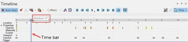
After the process starts, Composer™ creates images for every position frame in timeline. It starts from position 0, which is initial stage. To view various positions in timeline pane, you can drag the time bar and the position number highlights as we move the time bar. So for example if the total positions are from ‘Position :0’ to ‘Position :248’, then in total around 249 images will be created in the folder.
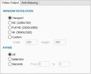
Now further the size of each image is same but varies as per our selection under ‘Window resolution’ option in Video output, for e.g. if we select resolution ‘Full HD’ size of each image would be around 7 to 10 mb, if we select resolution ‘4K’ size would vary in between 30 to 35 mb approximately. Further it may also vary as per other options or the content in particular frame like collaborative actors etc.
While the video creation is in progress, you can access this folder and check how the images are generated rapidly. Note that this is temporary folder and is deleted once the video is created completely.
To create video output without any issue, ensure that sufficient space is available in temp folder.
Noteworthy Solutions from the SOLIDWORKS Knowledge Base

Why do I see a dot or origin when I save or export a drawing to dxf/dwg?
SOLIDWORKS® R&D changed the behavior of drawings created in 2022. Before 2022, regardless of the origin visibility in the part, you always created drawing views with the origin hidden in the feature tree. To get more information, see Solution ID: S-079644
How do I enable the ‘Move with Triad’ option in SOLIDWORKS® 2022?
Starting from SOLIDWORKS® 2022, you can directly access the ‘Move with Triad’ option by selecting the component in the assemblies environment. To get more information, see solution ID: S-079647

When I open the SOLIDWORKS® Manage web interface, why do I see the message ‘There is no dashboard to display’ ?
After you configure a SOLIDWORKS® Manage incident on the server and then open the incident with the web, when you select the dashboard sometimes this message appears. To get more information, see Solution ID: S-079652

General Hotfix for DraftSight® 2022 SPO for SPR1227133 [Excessive memory usage by DraftSight triggered by commands like zoom inoutpancopy+paste]
To get more information, see Solution ID: S-079688
That’s it for this month. Thanks for reading this edition of SOLIDWORKS Support News. If you need additional help with these issues or any others, please contact your SOLIDWORKS Value Added Reseller.