

It’s that time of year again – the time of year where we spread joy with baked goods, presents, festive drinks, and decorations! In our last blog we used the power of the Weldments module in SOLIDWORKS to design and create a beautiful custom dragon yard decoration.
In today’s blog we will continue working on our epic decoration by lighting it up using the power of SOLIDWORKS Electrical and then we will render our creation in SOLIDWORKS Visualize so that we can truly appreciate its beauty.
As always, SOLIDWORKS Electrical provides an incredibly flexible workflow that allows us to jump between 3D and 2D as we want, or, if we have multiple engineers working on the same project, we can work concurrently. In this case, since there’s just one of us, let’s start in 3D.
Step 1: Quickly model a smaller LED, make it smart, and pattern it in an assembly with the dragon model previously created.
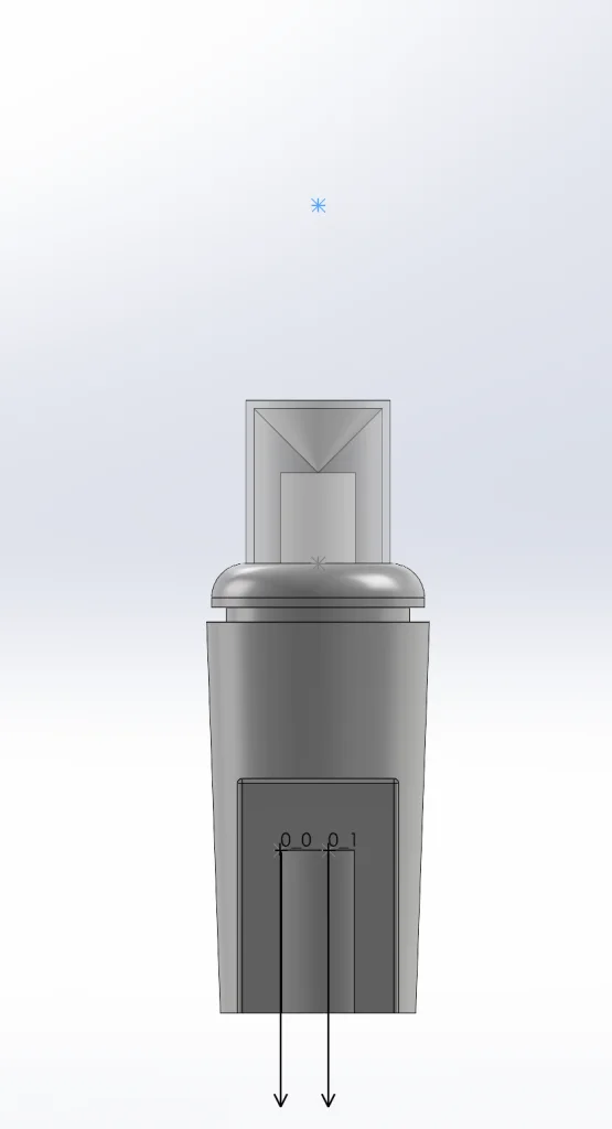
In order to fit a bunch of lights onto our dragon, we’re going to need a slightly smaller bulb. The good news is we can do this by quickly modifying the smallest bulb that we created to light up our house last year. This allows us to skip the steps of adding electrical intelligence and the base of the bulb is identical as well. To modify our part, all we need to do is Open it in SOLIDWORKS 3D, delete a few features, and add a Revolve feature with the correct dimensions. Then we can simply apply a translucent plastic appearance and a white LED appearance and we’re done! Here’s what our so-called Polka Dot Bulb looks like:
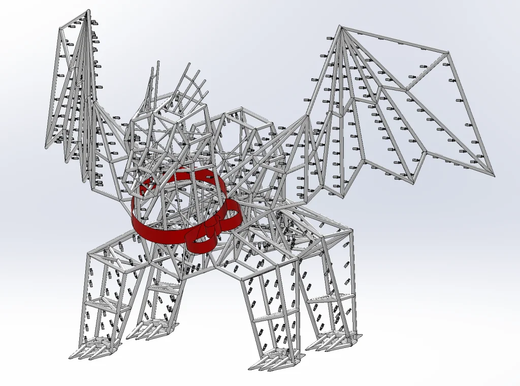
Perfect! Now we can create an assembly and insert this bulb wherever we want it. Let’s start by inserting our dragon and we can utilize patterns to get our bulbs exactly where we want them in no time at all.
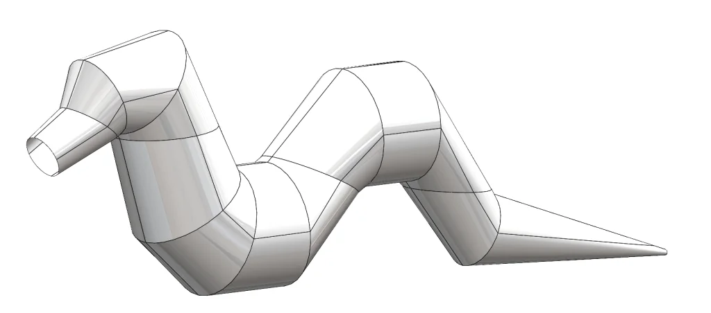
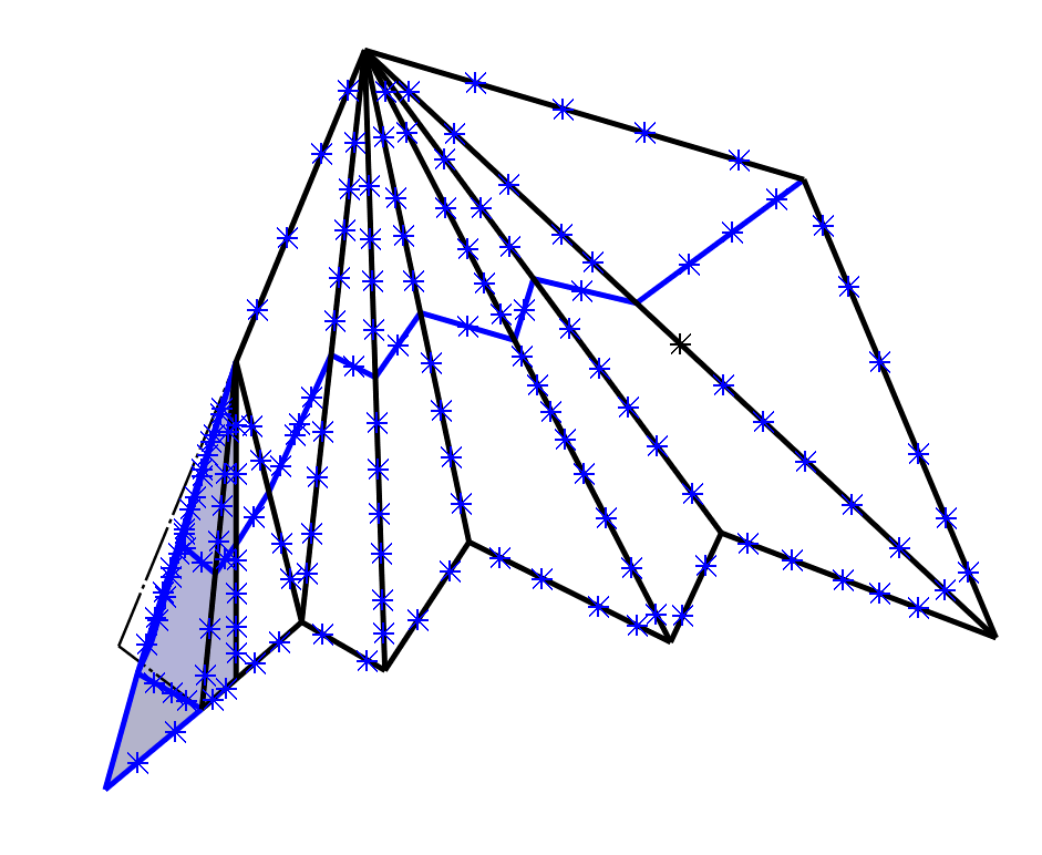
The first pattern I decided to use is the Curve-Driven Component Pattern for the body of the dragon. I did this by first creating reference surfaces in the original dragon model using Surface Loft and circular sketches at each section of the body.
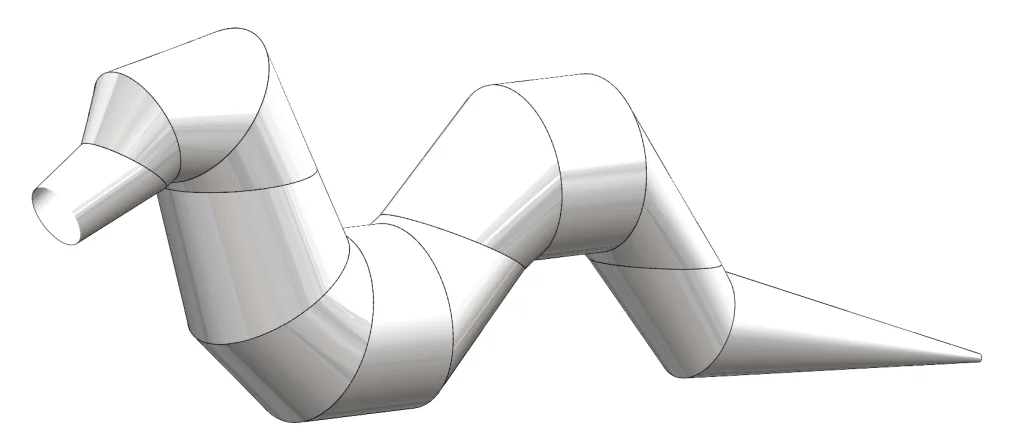
Then I used the Split Line feature to create curves in four quadrants around the body. These edges will become our curves for each Curve-Driven Component Pattern.
Next, all we need to do is return to the assembly and insert our Polka Dot Bulb 4 times around the quadrants of the dragon’s nose. Then we can use each of these components as the seed for a Curve-Driven Component Pattern.
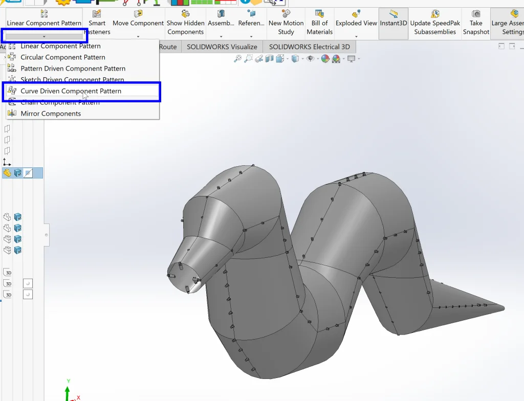
At the end of each edge, we can create a new pattern in the same way, using the last instance of the previous pattern as the seed. One thing to note here is that we want to select the option for Equal Spacing in the Properties dialogue box for the pattern and we will want to adjust the number of instances based on the length of the line. Additionally, for the left and right sides, we can utilize Mirror Components rather than redoing our patterns. This saves time and also ensures perfect symmetry.
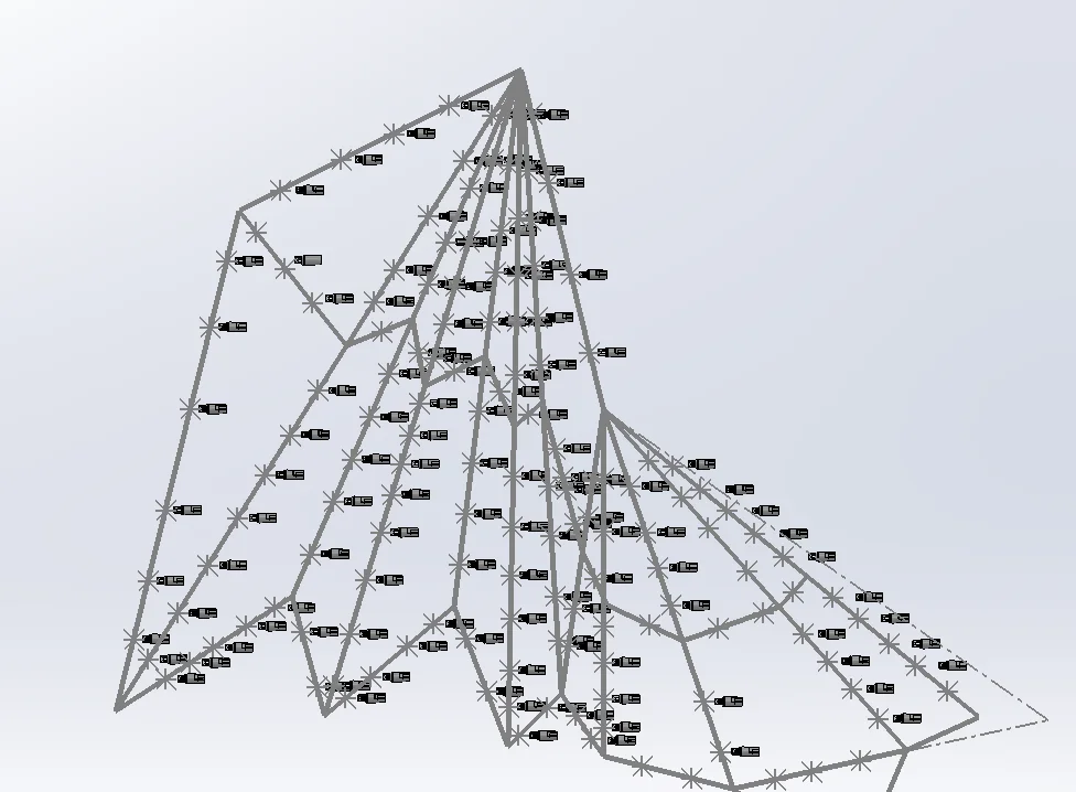
Now that our body is illuminated, we can move on to our wings and legs. To simplify things a bit, I decided to pattern these using a Sketch-Driven Component Pattern after modifying the original sketches (previously used to create the Structural Member features) to also contain points. Here’s what our wing sketch looks like after modification:
To create our pattern, all we need to do is insert an initial instance of our Polka Dot Light and then pattern it using a Sketch-Driven Component Pattern (Assembly > Linear Component Pattern drop-down menu > Sketch- Driven Component Pattern).
Instead of repeating this process on the other side, we can utilize symmetry again and simply Mirror Components.
This process is exactly the same for the legs, so I’ll spare you the details here, but we’re not done yet!
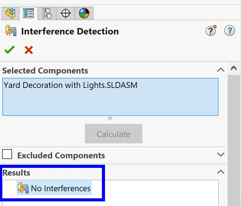
Before we can move on, we need to make sure that our lights are not interfering with our dragon model. We can do this from Evaluate > Interference Detection. After activating this command, we can see that we do have quite a few interferences, but no worries – we can fix these quickly by zooming to the interfering parts from the Properties dialogue box and either deleting them or modifying their position.
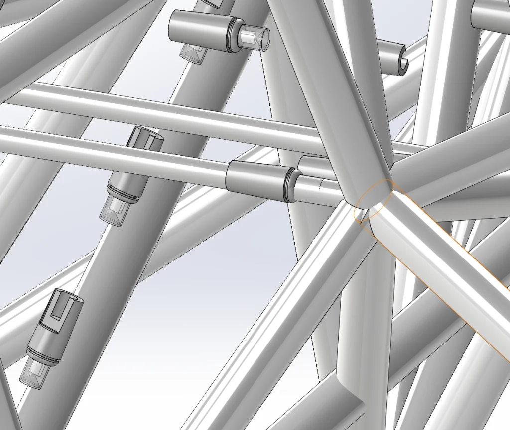
In the above example, I simply decided to delete the instance. In other cases, however, I decided to move a row of components quickly by selecting them in the graphics area and Right-clicking > Move with Triad. After making modifications and checking for interferences a final time, we can see that we now have No interferences so we can move on!
Note: After inserting all of the lights, I also quickly re-used our 3D models for male and female plug components before moving on to the next step.
Step 2: Make a new SOLIDWORKS Electrical Project from an existing project in schematics and modify
Again, as much as possible, we’re going to save time by re-using work that we’ve already completed. Luckily, we created a similar schematic package a year ago when we were working on lighting up our house, so we can start there and make changes as necessary.
From our Projects Manager in SOLIDWORKS Electrical Schematics, all we need to do is find the project we want to start with, Right-click and select Duplicate.
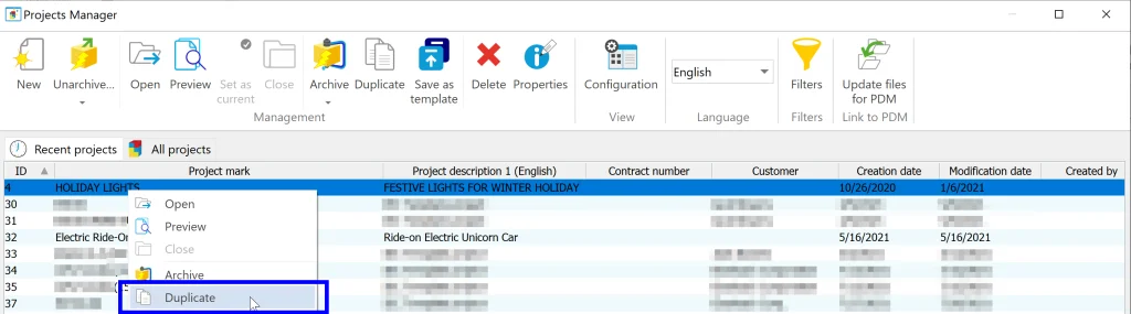
This creates a new project with all of the same content as the original, allowing us to rename it and then modify it (essentially a Save As Copy and Continue).
Now that we have a jump start, we can proceed to modify a few things and draw our schematics. Just as we did in 3D, we also want to create a new bulb in 2D by modifying an existing part. To do this, we can quickly open our Manufacturer Part Manager from the Libraries tab, search for our C9 bulb that we previously used, and Right-Click > Add manufacturer part….
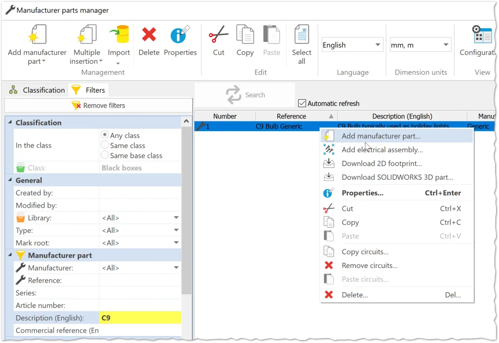
From here, we can change the name and properties of the part, deleting and adding information as needed. The great part about doing it this way is that (once again) we don’t have to add circuits and terminals because this remains the same!
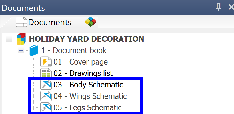
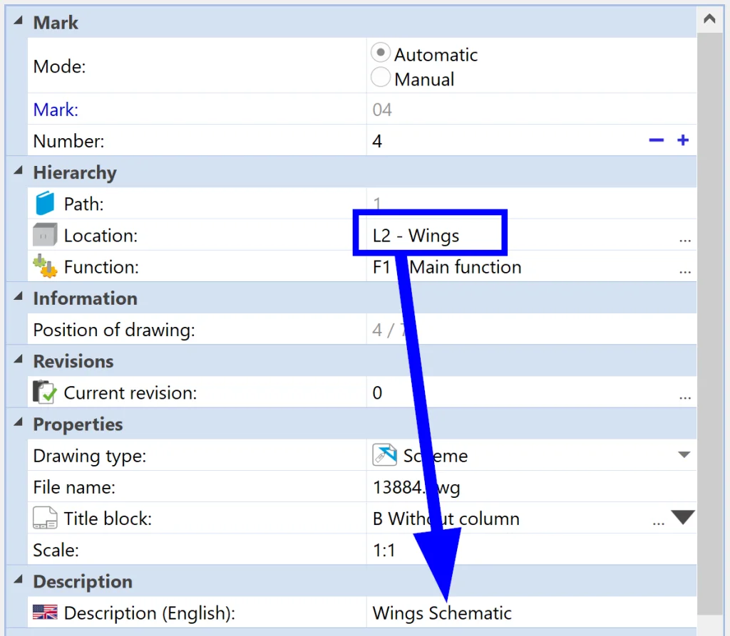
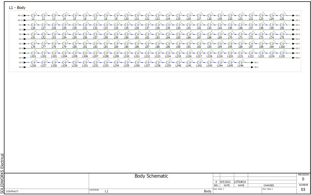
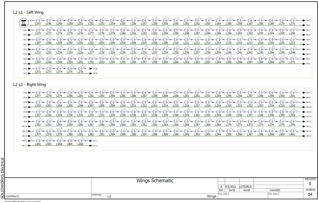
With our part completed, we can continue with our modification by renaming/adding/deleting schematics in our Document Tree. To rename, all we need to do is Right-Click a sheet and select Properties… before changing the Description (English) field. For the sake of organization, I decided to create separate schematics for Body, Wings, and Legs.
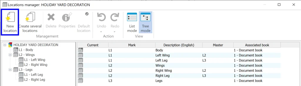
Speaking of organization, we can also organize our components by Location. This is the next thing we will modify. From Project > Locations, we can modify and add these before applying them to individual schematic sheets and components. I quickly deleted the old locations before adding new ones along with sub-locations. Sub-locations can be added by first selecting a “parent” location in the tree and then selecting New Location. Below you can see all locations listed along with their structure on the left-hand-side.
Now that we have defined our new locations, we can apply them to our schematic sheets with a simple Right-click on each sheet from the Documents tab > Properties. This allows us to change the location of all components on the sheet in one click, and it also sets things up so that when we add new components to our schematics, they automatically pop into the corresponding location.
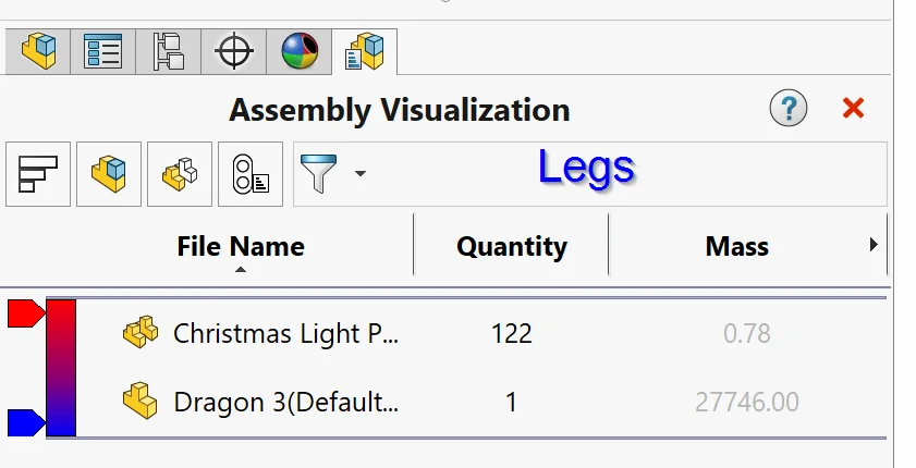
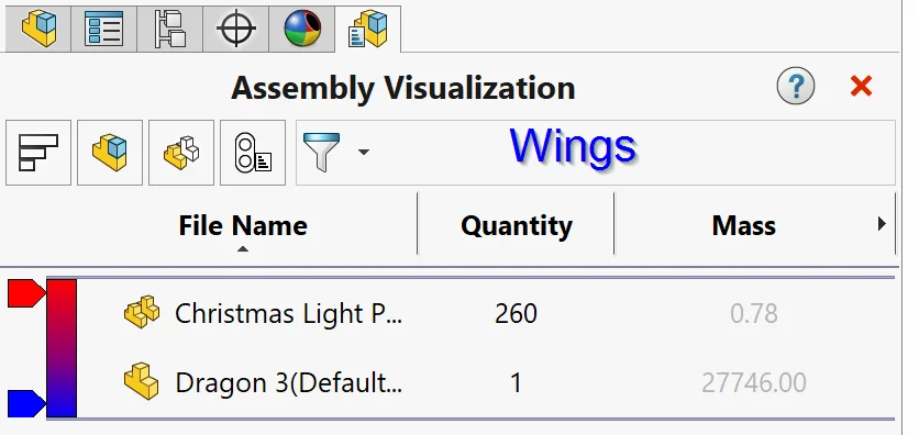
We’re almost ready to draw our schematics, but before we do we need to know how many light components to add to each location based on our 3D model.
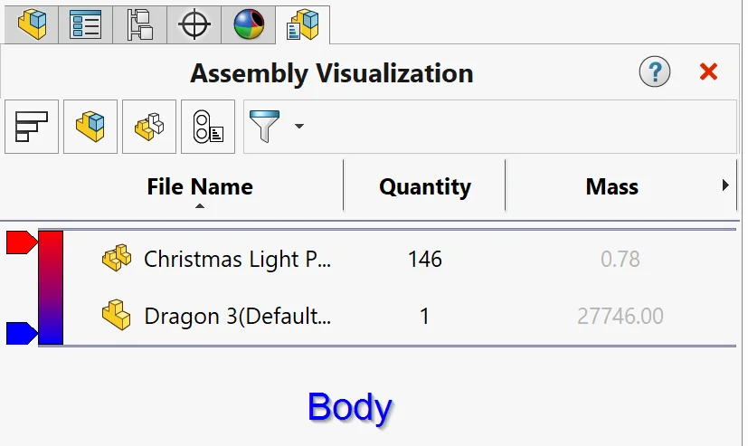
To figure this out, we’ll use a trick. Jumping back into our Assembly in SOLIDWORKS 3D, and switching over to the Evaluate tab, we want to activate Assembly Visualization. This command is incredibly powerful, and one of the things is does is group components together and count them for us. In this case, all we need to do is Suppress components to isolate components in a given area and then activate Assembly Visualization each time to get a quick count. Our results can be seen below:
Now that we know our component counts, we can jump back into SOLIDOWORKS Electrical Schematics and draw everything up! I started by deleting most of the symbols on the page from our previous project, leaving only a plug and one light. Then I double-clicked the light, selected the Manufacturer Parts tab, and made sure to switch out the Manufacturer Part for the one we previously copy/pasted/modified. By modifying this symbol up front, we can be sure that the correct part comes over when we copy/paste it in the next step.
We could simply copy/paste (Ctrl + C > Ctrl + V), but since we have so many components to create, we can save quite a bit of time using the Array function from Modify > Array. In this case, we only want one Row and 25 Columns with a spacing of .6 as can be seen below.
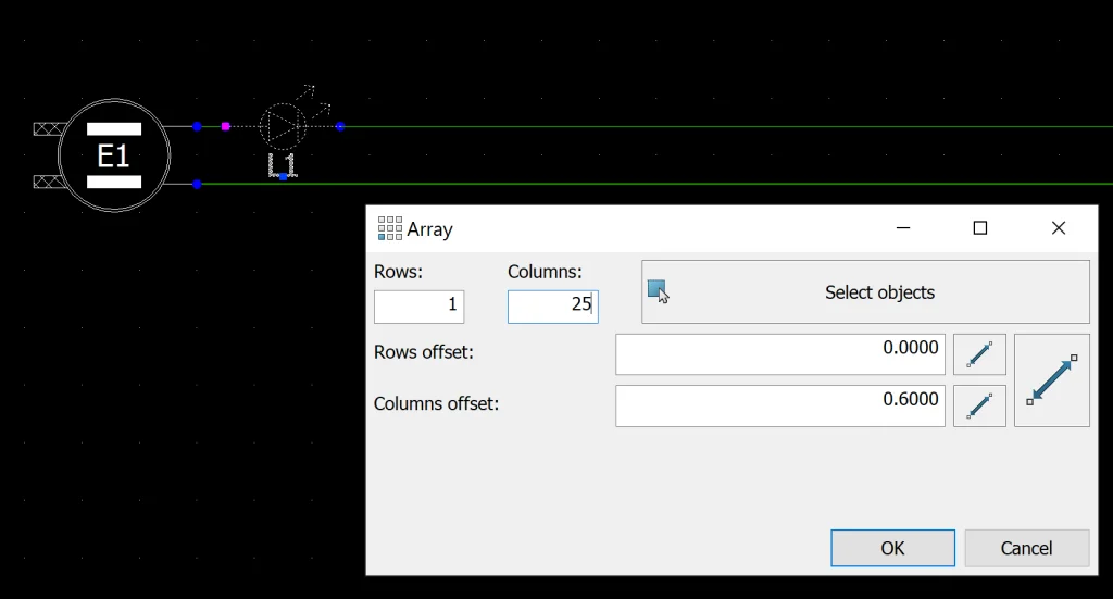
After doing this, we get a nice line of lights that is easy to count and keep track of.

From here, we can either use the Array command to create rows or we can simply select lights and copy/paste as needed. I opted for the latter because it seemed easier for me to keep track of the count this way. I also added Location Outlines (Schematic > Location Outline) as I went to further define sub-locations of components.
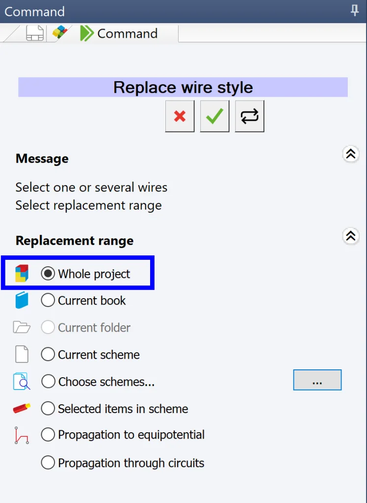
Next, I repeated this process for the remaining schematics before quickly Right-clicking a wire and selecting Wire style > Replace to grab a thinner, 22 AWG, wire. I selected Whole Project as the scope of this command since this is the only wire style we need here so far.
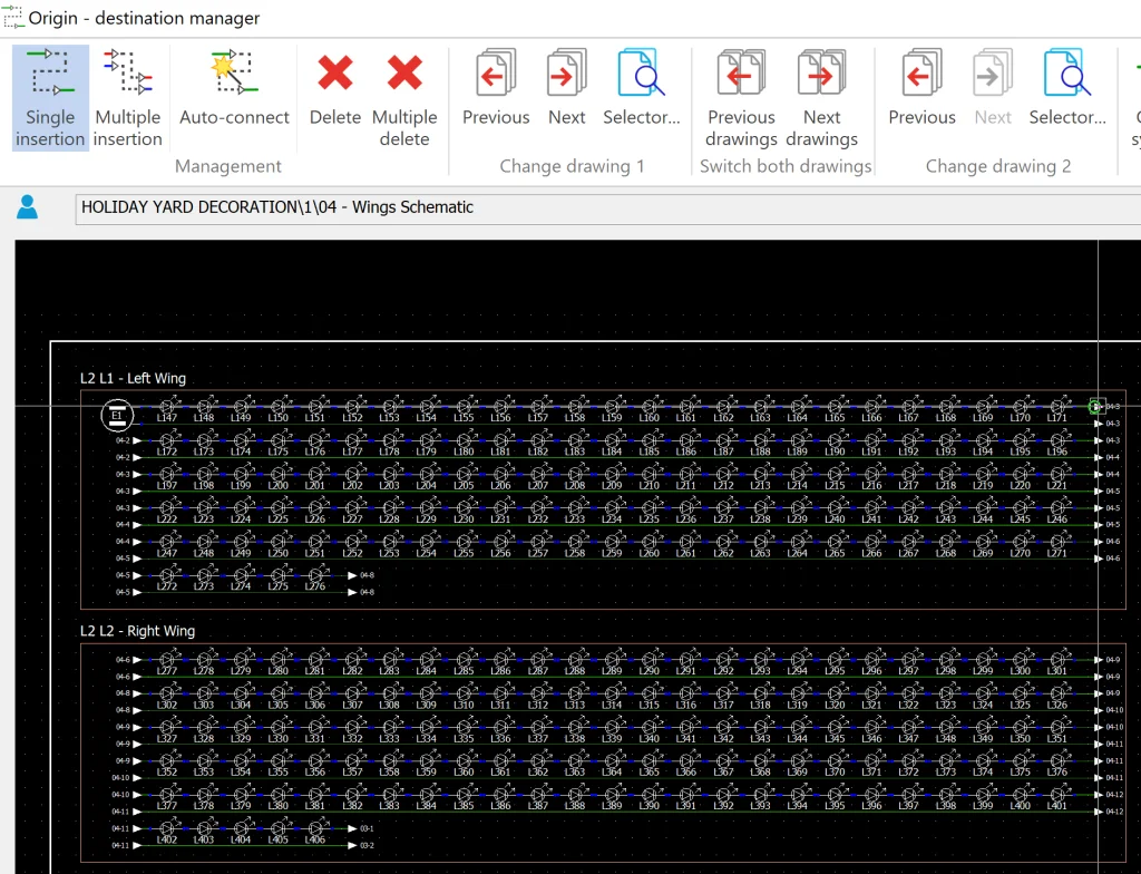
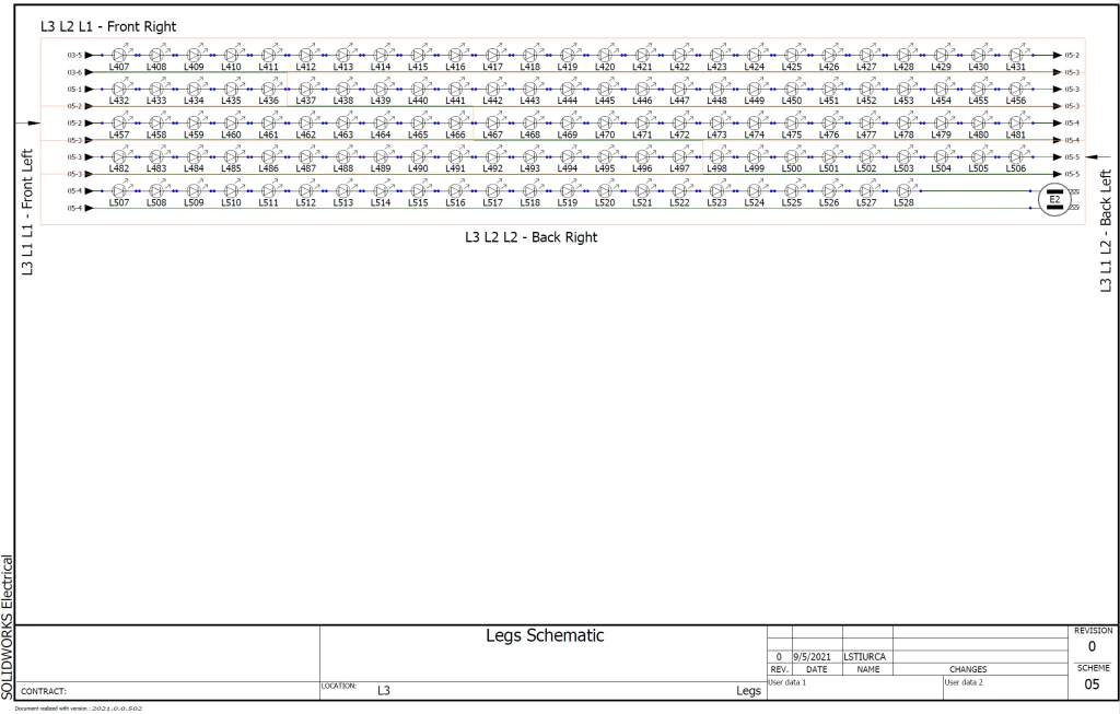
Fantastic! We’re almost done drawing our schematics. Now all we need to do is connect wires using Origin-Destination Arrows. After looking at our 3D model, we can see that one logical way to connect different locations is to start with the female plug and then connect Wings > Legs > Body > male plug, with the final wires extending from the tail of our dragon. Schematic > Origin-Destination Arrows makes connecting wires super quick and easy. All we need to do is select Single Insertion and start clicking. SOLIDWORKS Electrical highlights wire ends that match for us, adds arrows, and ultimately adds hyperlinks for us as well automatically.
We’re done! Now that our schematics are drawn, we can quickly create an associated assembly from Process > SOLIDWORKS Assembly, selecting to only create the top-level assembly as we did before.
Note: Before doing this, I deleted the copied assembly that was previously made for our house project.
Step 3: Take our basic mechanical assembly and make it electrically “smart”
Jumping back into SOLIDWORKS 3D, we want to make sure that our SOLIDWORKS Electrical Add-in is activated (Options drop-down > Add-Ins > SOLIDWORKS Electrical). Then, from the Task Pane on the right, we can select the SOLIDWORKS Electrical tab and Right-click the white background to open the Projects Manager. This allows us to open the same project we were working on in SOLIDWORKS Electrical 2D, and, from here, we can double-click our assembly to open it.
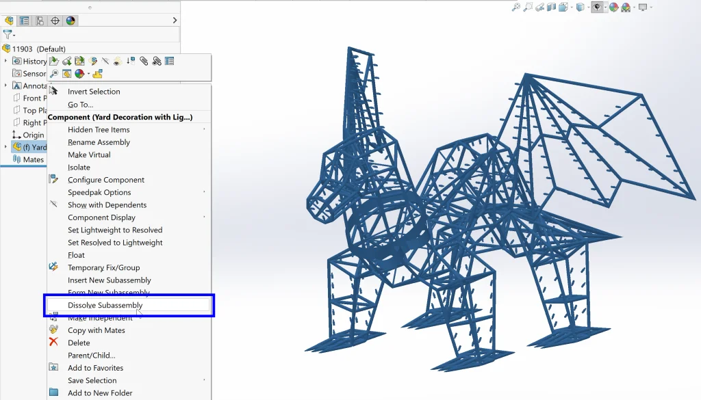
Since we’ve already completed most of our work in SOLIDWORKS 3D without the add-in activated, all we need to do now is insert the assembly we completed earlier here (Assembly > Insert Components) and then Right-click our assembly in the FeatureManager Design Tree > Dissolve Subassembly to bring all of our components up to the top-level assembly.
Note: This is a trick you can also use if you have legacy models created in SOLIDWORKS before obtaining a seat of SOLIDWORKS Electrical 3D.
Now all we need to do is Associate our previously inserted 3D models to the components we added in SOLIDWORKS Electrical Schematics. This may seem daunting as there are around 500 lights in our assembly, but SOLIDWORKS Electrical makes it super easy and it ends up saving us SO MUCH time down the line that it’s worth it. All we need to do here is Right-click > Associate from the component tree based on location and flow. SOLIDWORKS Electrical helps us keep track of where we are by changing the transparency of already associated components. Below you can see a quick video of a portion of the process:

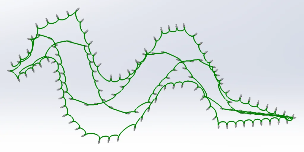
Fantastic! This project is really coming along. With all our components associated, we’re ready to start wiring everything up. With such a huge number of components, however, it’s wise to test things out before fully routing. To do this, we can go to SOLIDWORKS Electrical > Route Wires and select the option to only route Selected Components. Additionally, we can specify to route as a Sketch rather than as a SOLIDWORKS Route. This reduces the amount of time needed to route and allows us to troubleshoot as we go. Here’s what it looks like if we just select to route the components along the body using the above method:
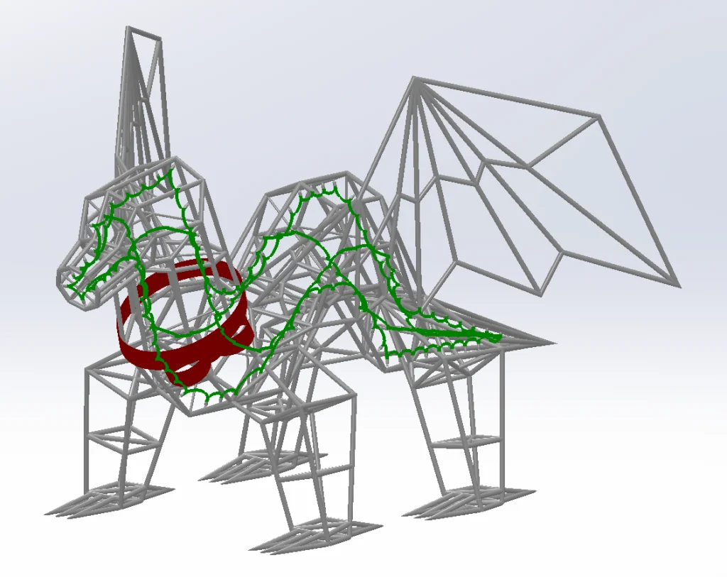
As you can see, SOLIDWORKS Electrical handles this portion perfectly, even without a Routing Path. In fact, using this method, we can see that, for the MAJORITY of our model, no Routing Path is needed. That being said, after routing our entire assembly using a Sketch Route, we can ALSO see that connections between locations and out to our plugs DO require some guidance in the form of a Routing Path, so let’s draw that now.
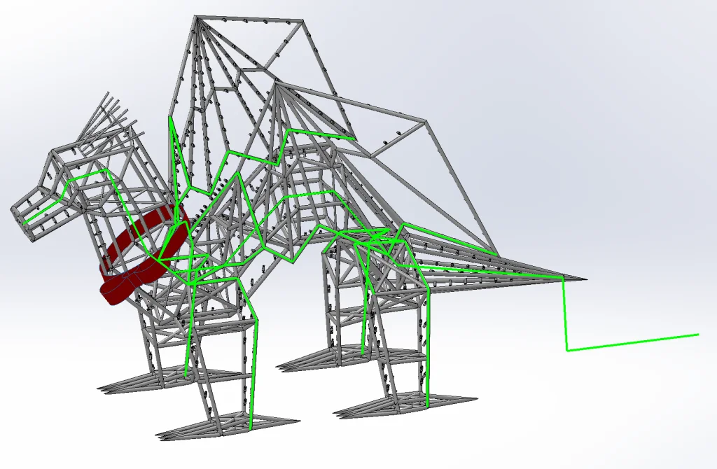
To do this, all we need to do is go to SOLIDWORKS Electrical 3D > Create Routing Path and select to create a new 3D Sketch. Then we can dig into our original dragon model and re-use sketch segments using Convert Entities to create the following:
Perfect! Except… how do we selectively apply this path to certain wire segments? If we route as-is, many of our wires will end up being needlessly long in an attempt to “follow the path.” Luckily, I have another trick for us!
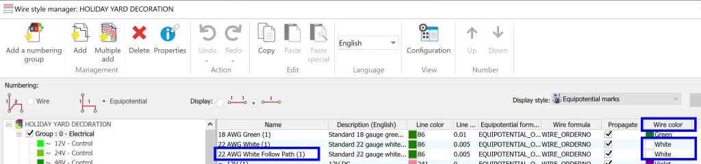
First, we want to jump back into SOLIDWORKS Electrical Schematics and create a new wire style specifically for wires we want to follow our routing path. While we are at it, we can also modify the Color for both wire styles to blend in with the rest of our model (change from Green to White). All of this can be done from Project > Configurations drop-down menu > Wire styles…. Below you can see the modifications made along with the new wire style:
The next key part in this trick is finding the connecting wires that we need to follow this path and replacing them by Right-Clicking > Wire Style > Replace. In this case, we only want to Propagate to Equipotential rather than replacing every wire in the entire project.
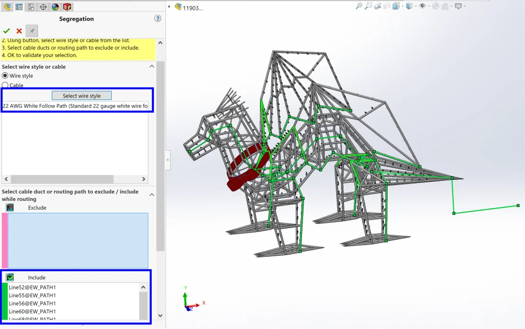
Finally, back in SOLIDWORKS Electrical 3D, we can use the Segregation command from SOLIDWORKS Electrical 3D > Segregation to Include our new wire style for each of our route segments and Exclude our original wire style form each of our route segments.
Perfect!
Step 4: Route wires and update Reports
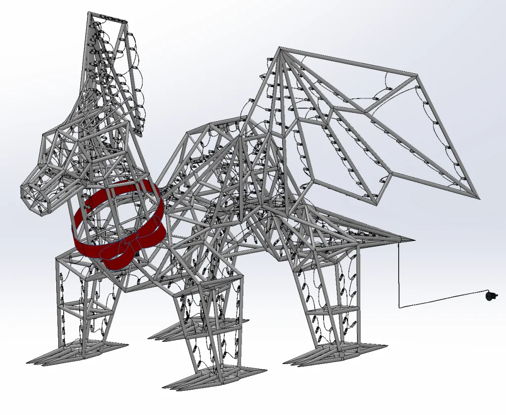
Now that everything is in place, we can Route Wires one more time, but this time we can select All Components and use the SOLIDWORKS Route Option to create actual physical wires between our components. Since we have a TON of components, I decided to run the command and forget about it for a bit while I went to cook dinner. I want to point out here how grateful I am that we don’t have to do this manually for over 500 individual parts. While I baked some enchiladas, SOLIDWORKS Electrical looked at the schematic, found each and every component, grabbed our wire color and diameter, looked at our routing path, and connected everything together perfectly for me automatically. If I didn’t know any better, I would say this was actual magic.
Fantastic! Everything looks amazing. Now all we need to do is generate a few reports and get a nice image of our epic decoration using SOLIDWORKS Visualize. Let’s tackle the reports first.
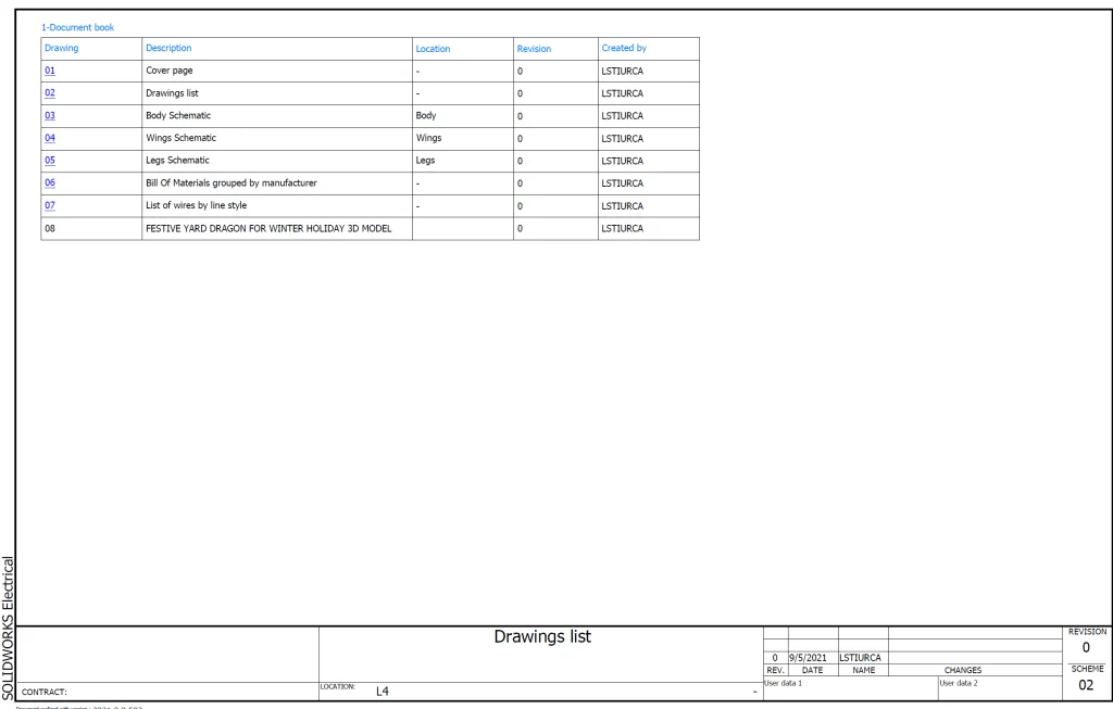
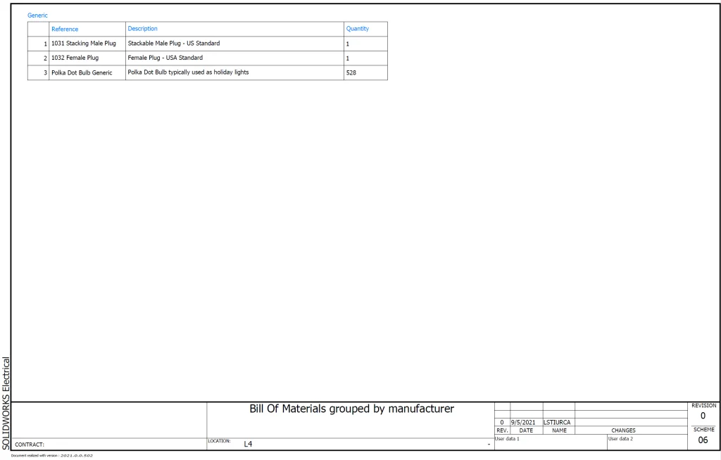
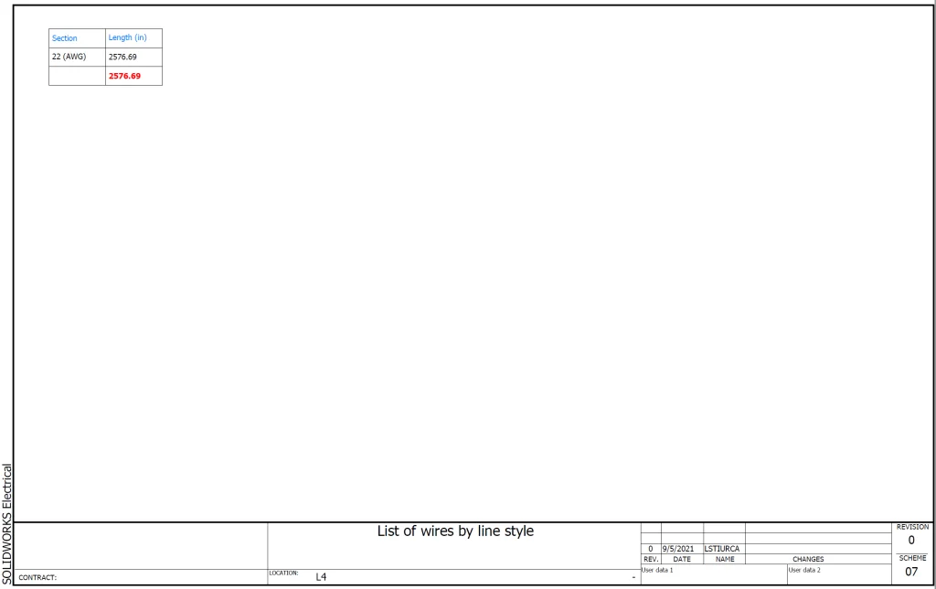
Back in SOLIDWORKS Electrical Schematics, we can jump over to the Project tab and select Reports before selecting Generate Drawings. It’s literally that simple. Our reports are generated and added to our Documents tree automatically. Now we can see that we actually have 530 components total and about 215 feet of rope.

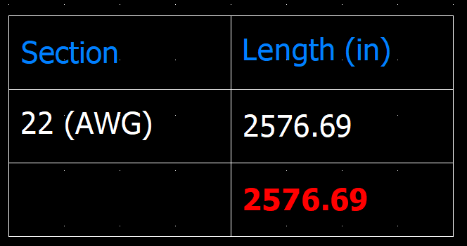
Note: The wire length calculation includes 10% slack. I added this to my report previously by modifying the equation for length to include a 1.1 multiplier. In the same way, we could have chosen to display our length in feet and inches with a quick equation modification.
Step 5: Render in SOLIDWORKS Visualize
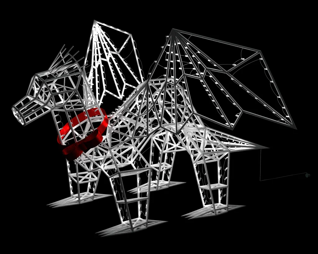
Now that we have everything exactly where we want it, it’s time to make it pretty and get a good idea of what this magnificent beast will look like in real life at nighttime. The quickest way to do this is from the SOLIDWORKS model itself. As long as we have the SOLIDWORKS Visualize Add In activated, we can simply jump over to the SOLIDWORKS Visualize Tab and select Export Advanced to quickly send everything over. This automatically opens SOLIDWORKS Visualize for us and creates a project with our assembly already inserted.
From here, I quickly updated/upgraded a few appearances (simple drag/drop) including the satin ribbon and the brightness of the LED bulbs (I made this appearance brighter) before modifying the environment.
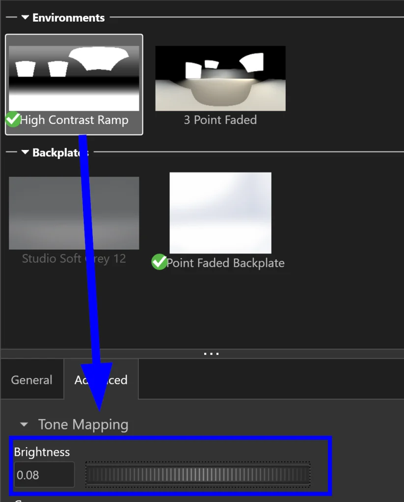
In this case, we want to see what our dragon will look like at night, so, from the Environment tab, we can start by deleting all of our directional lights and setting the Brightness of our Environment to 0.075 from the Advanced tab.
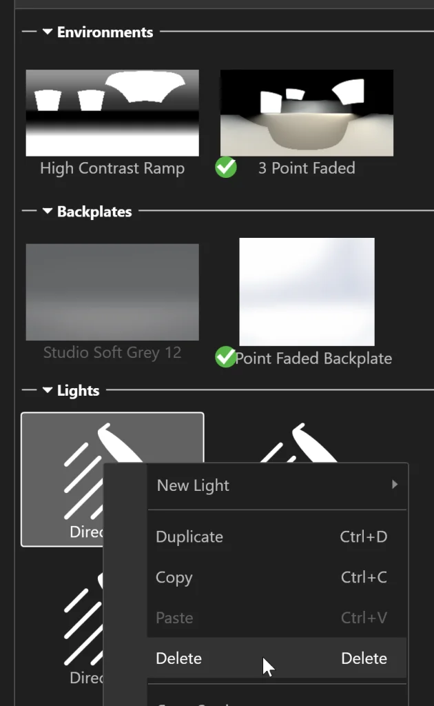
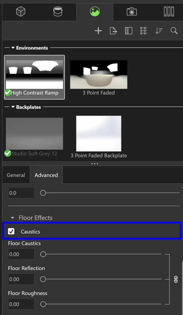
We can also change our backplate to something a bit darker or set it to a plain black color, but the *most important* thing we want to do is modify the Environment and turn ON Caustics (also on the Advanced tab). I’ll show you why this is so important in just a minute.
To demonstrate the difference that Caustics makes, I went ahead and rendered the model first with it turned off. You can see the result below:
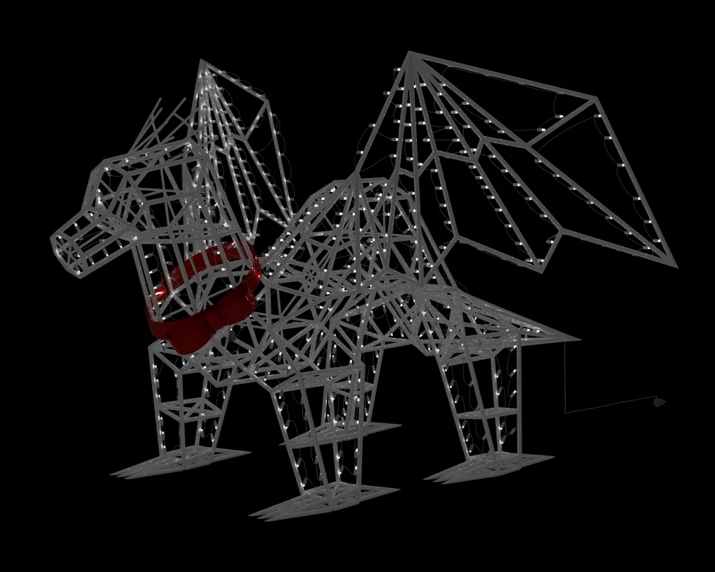
Underwhelming, right? Here’s the same exact thing modeled with Caustics turned ON:
INCREDIBLE difference! The reason for this is that caustics/optics are the thing that tells the program to calculate how light bounces off of the model. In a model like this, the feature is ESSENTIAL, so don’t forget to turn this feature ON!
The last thing that we might want to do here is add our own Backplate. We can do this by right-clicking in the Backplate section on the Environment tab and selecting New Backplate…. This allows us to select a picture from our machine to use as the background for our image. Here’s a nice look at our dragon in front of a lit-up house:

… and a turntable render as a bonus:
Our dragon looks AMAZING! The very last thing I want to do is add a nice image of our rendered dragon to our Schematics title page. To do this, all we need to do is find the image we want to use, Save As… a bitmap (.BMP) file, and then jump into SOLIDWORKS Electrical Schematics and, from the Cover Page, select Draw > Insert Image. This allows us to insert a nice picture onto our cover before we Export to PDF. Here’s a quick look at our final document package after exporting:

We’re done! Thank you so much for following along. I had a ton of fun designing this and I hope you had some fun reading and learned something new. Wishing everyone a Happy Holidays and a wonderful New Year to come!