

Last year we lit up our house for the holidays using the power of SOLIDWORKS and SOLIDWORKS Electrical. It was a lot of fun and it spread a lot of joy. This year, we’re hoping to add to our décor (and joy) with an EPIC yard decoration that matches our personalities – a DRAGON! Unfortunately, after an extensive search of the interwebs, I found no such preexisting yard decoration. I did find a unicorn, bear, penguin, and deer, but I felt we could do better. Fortunately, we are creators. Making epic ideas come to life is what we do!
In this blog and the following blog, we will make our own dragon yard decoration. In part one we will conceptualize and model the dragon using the power of Weldments in SOLIDWORKS. In the second part, we will light it up using SOLIDWORKS Electrical and rendering everything using SOLIDWORKS Visualize.
Let’s get started! The first thing I did was make an *incredibly rough* sketch of the side profile we’re going for. I am not an artist. If you are, please message me and we will collaborate on future projects.
I then scanned it into my smartphone, emailed it to myself, removed a number of smudges in the background, and inserted it into a new SOLIDWORKS part on the Front Plane by opening a Sketch and going to Tools > Sketch Tools > Sketch Picture.
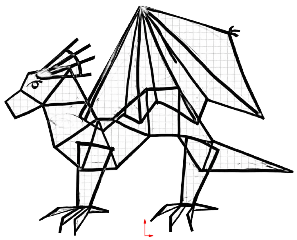
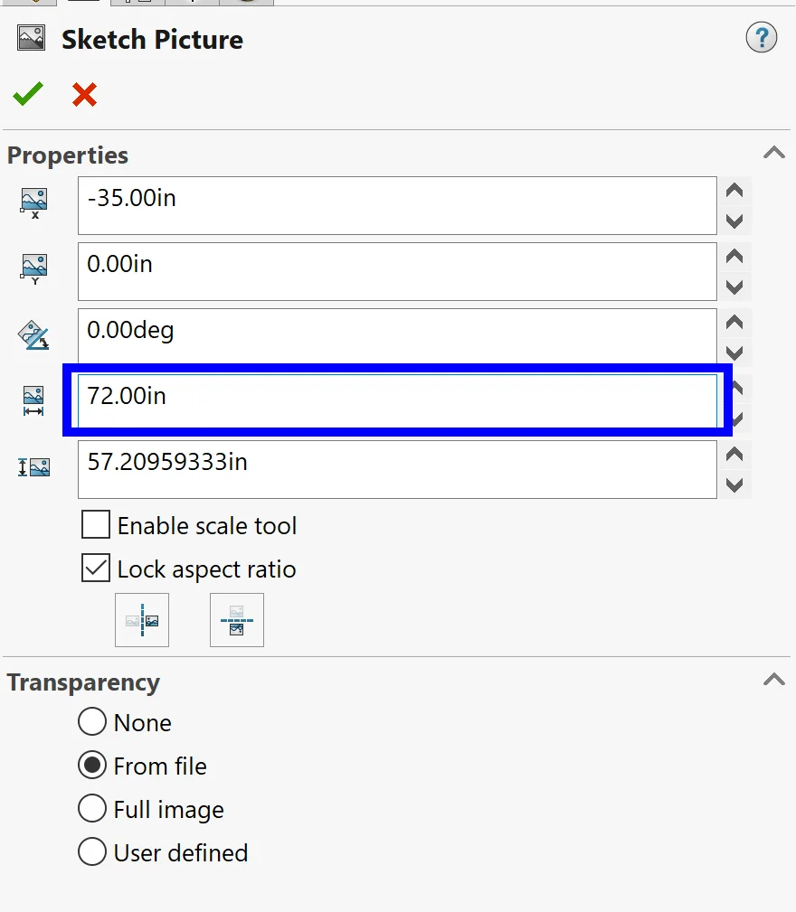
I also set the length of the beast to 72” and aligned the picture so that the point of the wing would be above the origin.
Now that our sketch is inserted, the next step is to make the body. I started this process by tracing just the body of the dragon from the sketch before hiding the sketch itself so that it wouldn’t distract. Then I added a centerline thinking I might use it in the future for support.
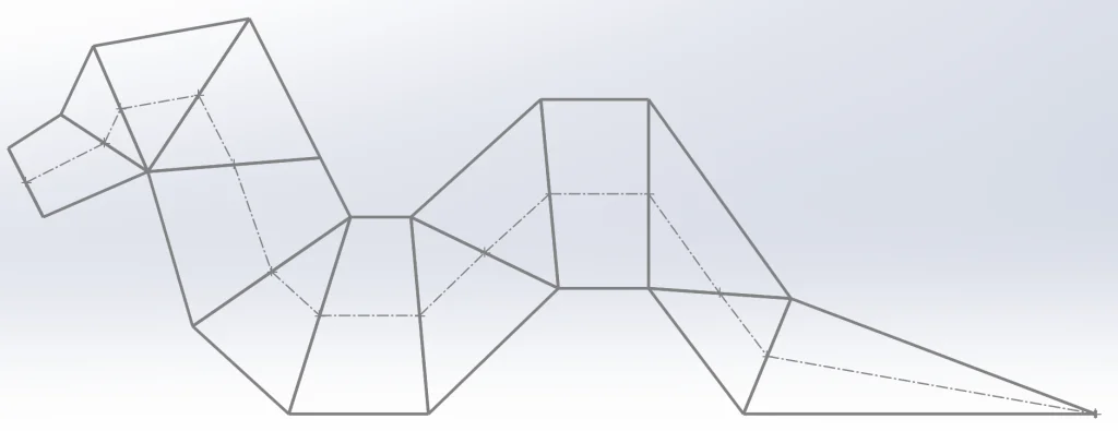
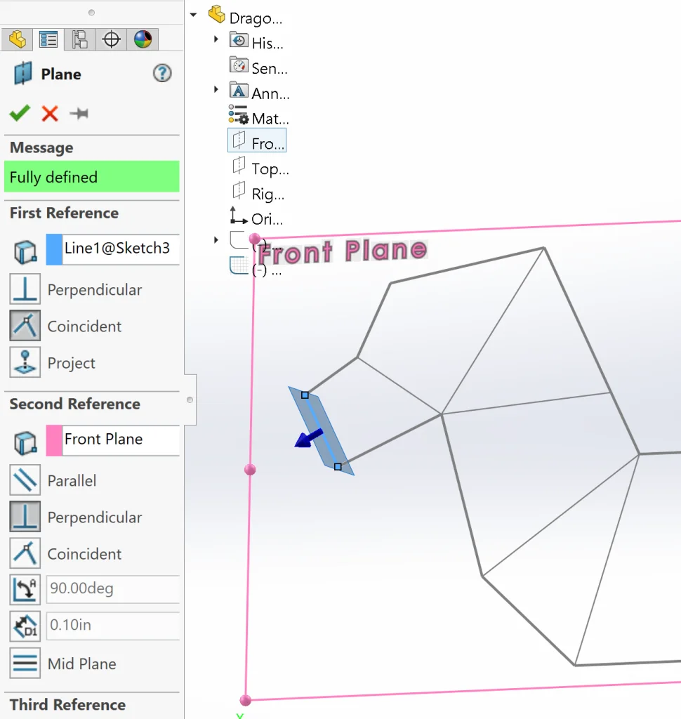
To bring this profile into 3D space, I started by creating planes (Features > Reference Geometry > Plane) along each “support line” (everything except for the outside profile, excluding the nose line). This part is simple. All we need to do here is grab the line and the Front Plane to define the new plane… and repeat.
Here’s what this step looks like once we are finished:
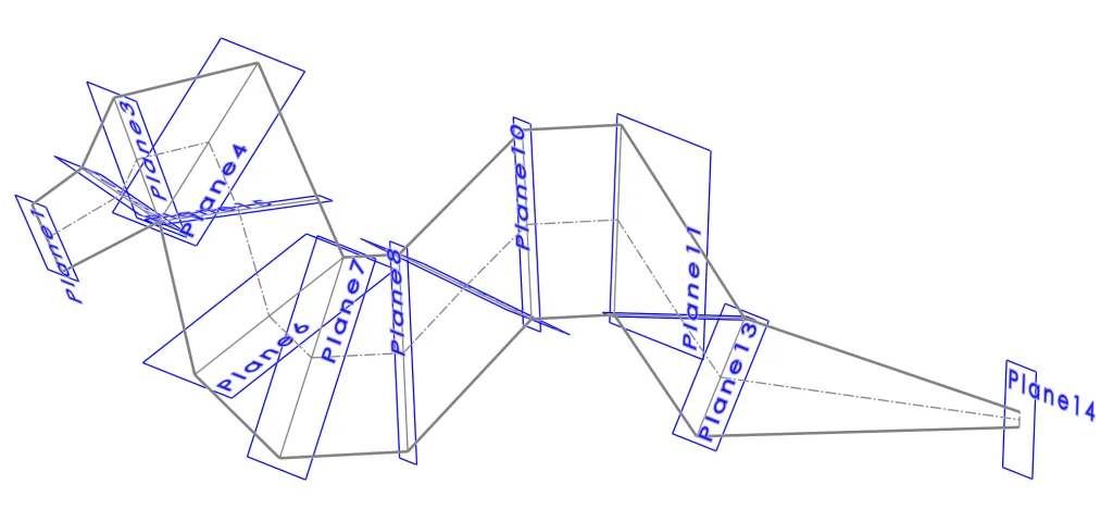
Next I created octagons on each plane with a diameter equal to each of the “support lines” and connected vertices for future use in creating some structural stability.
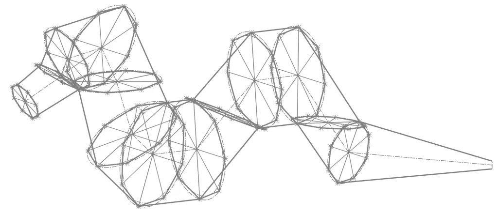
This brings everything into 3D space, allowing us to create a 3D Sketch and connect vertices to get some real structure.
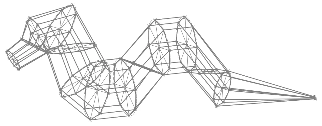
This is already looking promising, but we need to add some actual material still. To do this, we can use the Weldments features in SOLIDWORKS. In this case, I went ahead and looked up the material I want to purchase for this project – ½” and ¼” cylindrical rods. I didn’t immediately find an existing Structural Member that matched the profile needed, so I quickly created my own using the following steps. (Note: These steps can also be found in more detail on the super handy SOLIDWORKS Help page HERE)
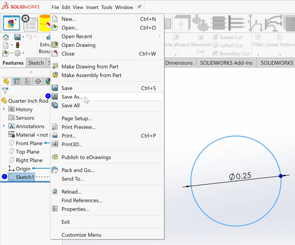
- Open a new part and sketch the profile needed.In this case, we simply need a circle with a ¼” diameter – easy peasey!
- Close the sketch and *select it in the FeatureManager design tree* before selecting File > Save As.
- From the menu, browse to install_dirlangEnglishweldment profilesANSI and create a couple folders to define type. For most standard installations, install_dir can be replaced with C:Program FilesSOLIDWORKS CorpSOLIDWORKS.In this case, I created a folder called “Standard” and one called “User.” I put all of the standard ANSI profiles into the Standard folder and saved our new profile as a Lib Feat Part (*.sldlfp) in the User folder.
- Repeat this process with a new part for our ½” diameter profile.
Now that we have created our custom weldment profiles, it is time to use them! To do this, all we need to do is activate the Structural Member command and select “Standard: ANSI, Type: User, Size: Half Inch Rod” before starting to select segments. In the case of these structural members, we could start by clicking on a random line, but it’s actually better to do things in an orderly fashion. Each Group of sketch segments defining a path must contain either consecutive lines or parallel lines, so I started by selecting lines defining a full octagon. After selecting this Group, I clicked New Group from the Properties Manager and proceeded with the next octagon until all octagons were defined in the command. Finally, I selected groups defining the length of the dragon.
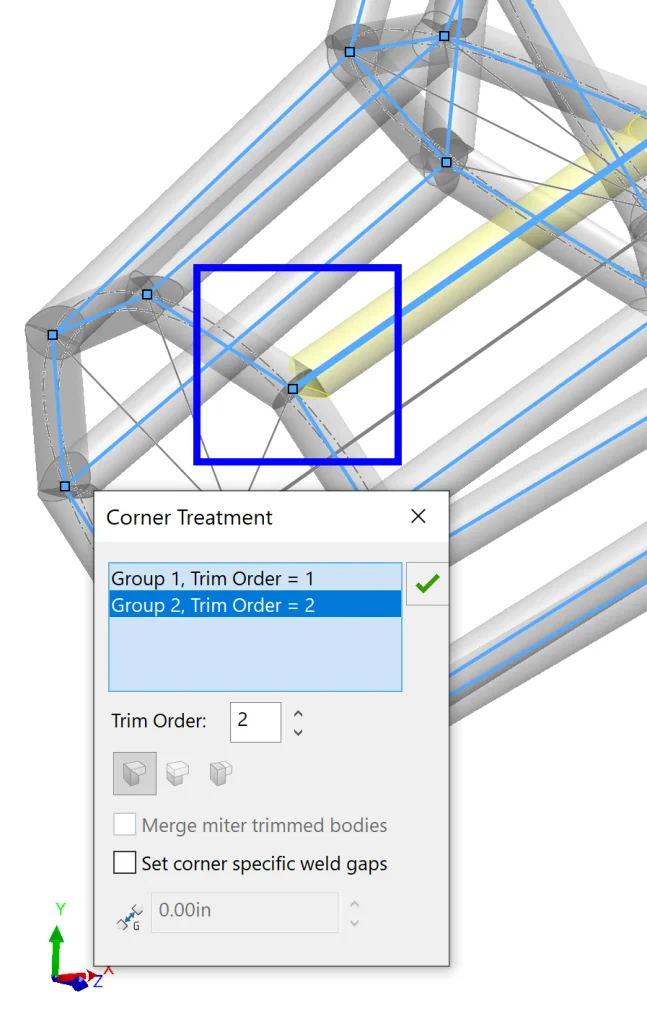
We’re almost done creating the body, but there’s one more thing to consider here: the Trim Order. Any time a corner is created, we can click on it in the graphics area to take a closer look at Corner Treatment. This allows us to select the order in which pieces are trimmed together at each vertex. I also like to think about it as priority – a group with Trim Order of 1 has priority over a group with Trim Order of 2, so the group with Trim Order 2 will be cut to accommodate the group with Trim Order 1.
Below we can see what a simple corner looks like with Trim Orders 1 and 2 applied.
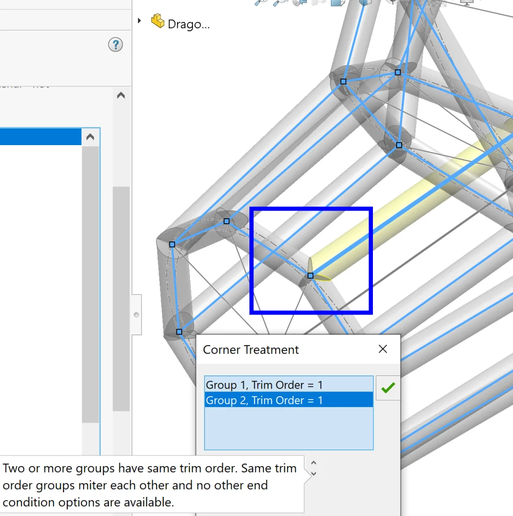
Cool cool, but what if we want to miter everything together evenly? The answer is simple – all we need to do is change the Trim Order of Group 2 to equal that of Group 1 (Trim Order = 1). Here’s what this looks like:
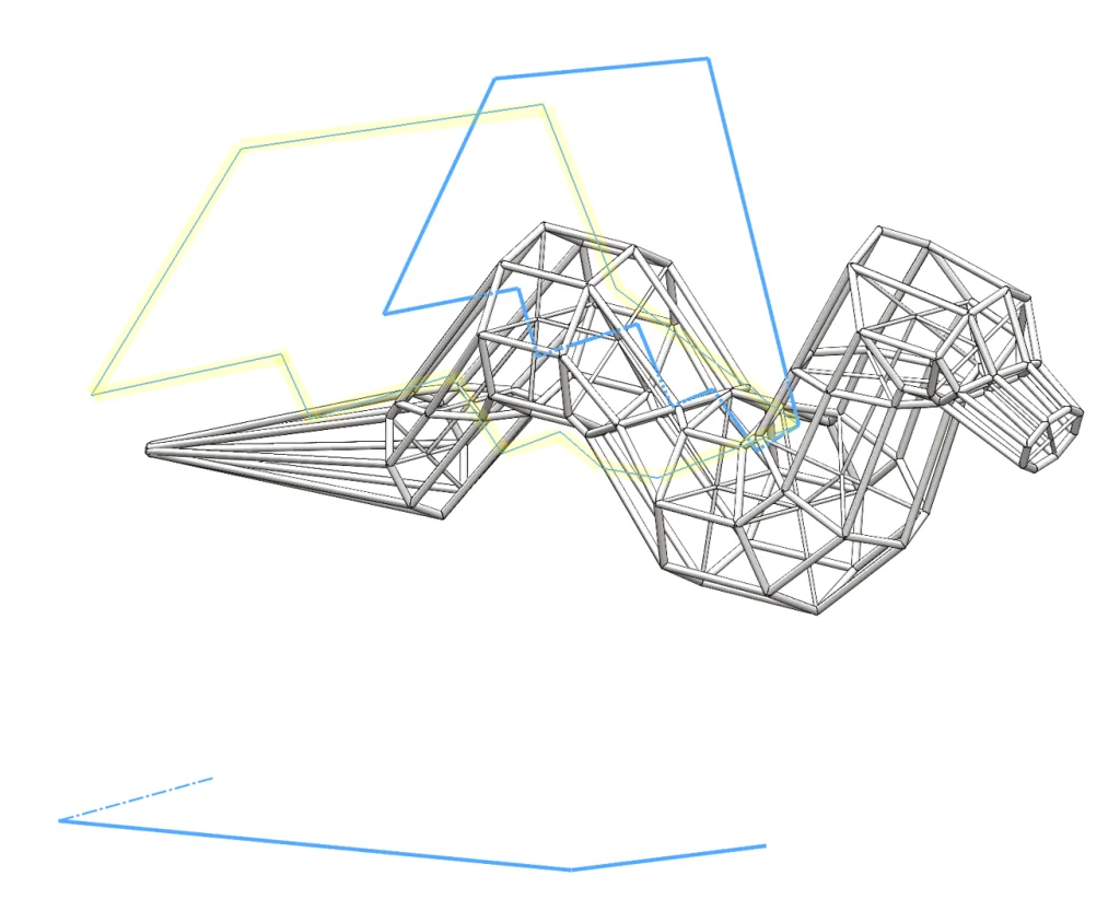
I went ahead and modified a few of these vertices quickly before hitting the green checkmark to accept the command. Then I repeated the process for some of the inner dragon skeleton/support pieces using the ¼” rod. Here’s what it looks like after adding all of our structural members:
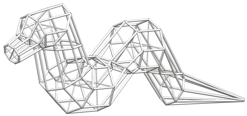
It’s a snake! Very good – time to add some wings and make it a flying snake!
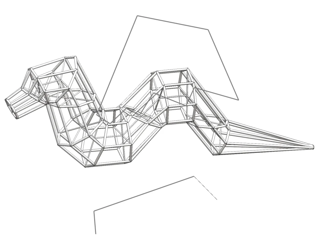
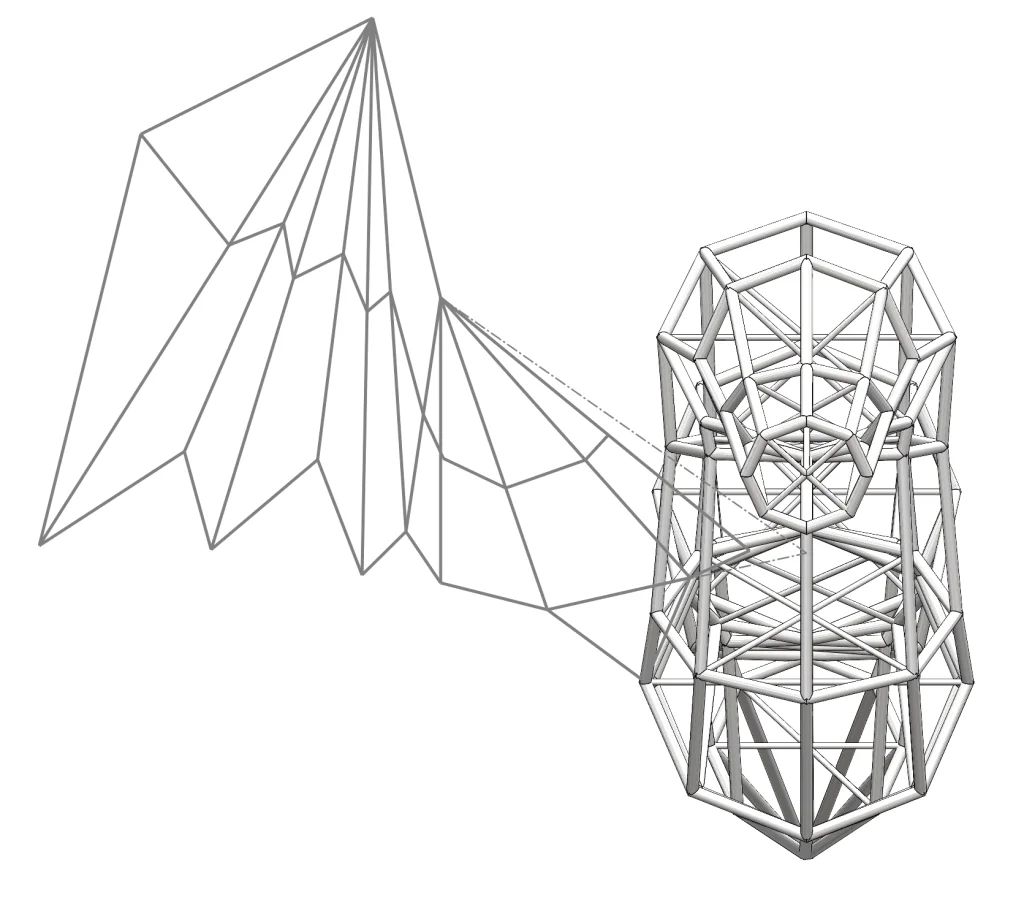
To add the wings, I took a slightly different approach. First, I loosely traced the wing from the original sketch. Next, I sketched the wing shape (freehand) on the top plane, making sure that the endpoint of this top-down sketch aligned well with the end of the first sketch. Here we can see the two sketches in context:
Now that we have these, we can use the command Project Curve (Features > Curves > Project Curve) to combine the two flat sketches into a 3D curve defining wing shape. To do this, all we need to do is activate the command, select Sketch on Sketch and select the two sketches we made. Here’s how it turns out:
Perfect! Now we have a great base for our wing sketch. The next step is to open a 3D sketch and use Convert Entities on the curve we just created. Now that it is in a sketch, we can add lines to represent support and modify the existing lines so that our wing will attach neatly to the body.
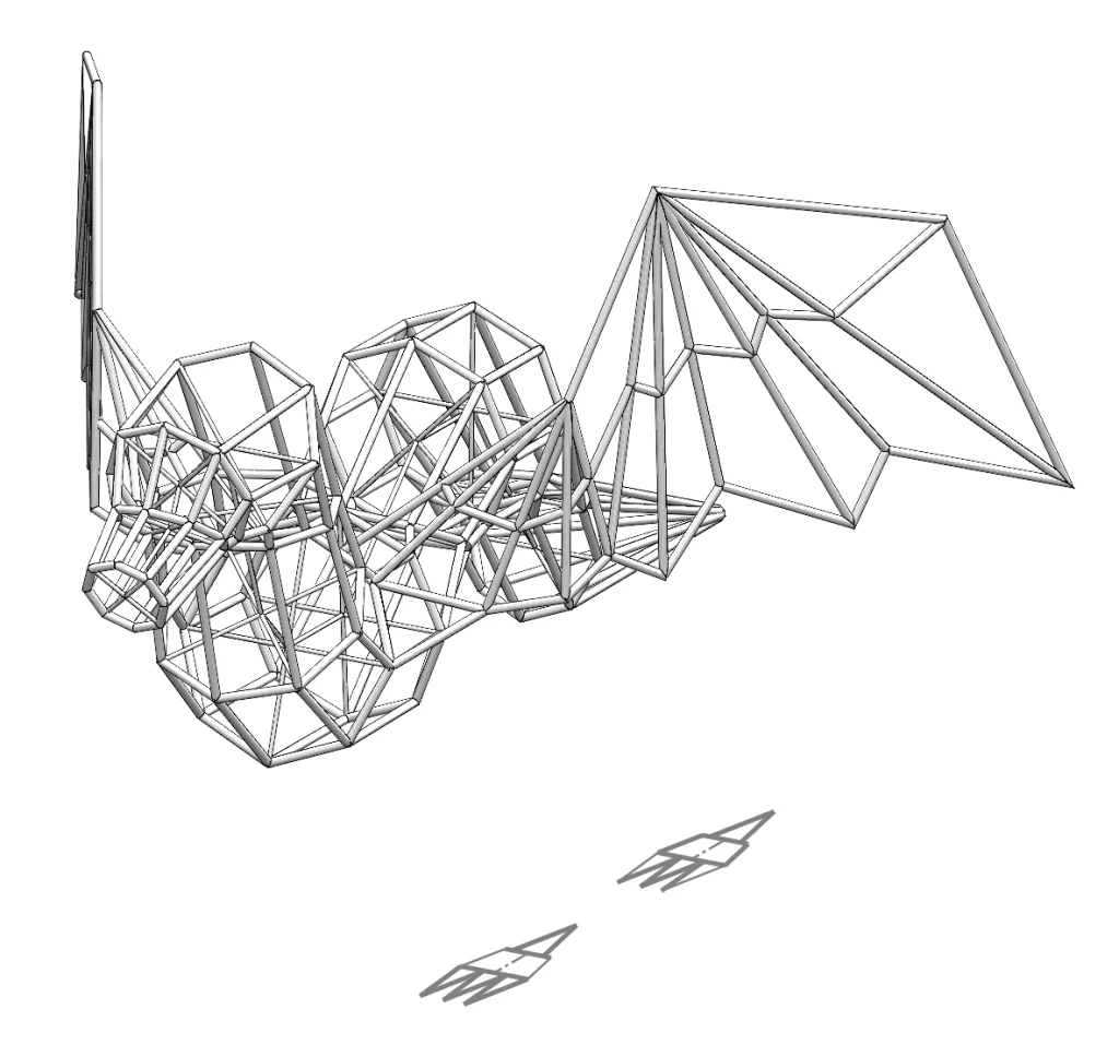
Excellent! Our wing is almost done – all we need to do now is use the Structural Member command again with our ½” rod to bring it to life. Once this is done and we’ve adjusted corners as we did before, we can use the Mirror command to turn a single wing into a pair.
Awesome—now we have created a majestic flying snake!

Perfect! Now all we have left are some dragon legs and a bit of decoration. Let’s get started on the legs.
For the legs, I started with a 2D sketch on a plane parallel to the Top Plane and then finished with a freehand 3D sketch from there. A few tips I always like to share when it comes to 3D sketching:
- Always start at a known point. If you don’t have any geometry yet, the Origin is a great place to start.
- Use TAB to change directions and rotate your model to understand where you’re going.
- After creating sketch lines, if you need to modify your sketch, Right-Click and select Show Sketcher Triad to move points with greater precision.
- Use Construction Lines as much as possible if you need to add curves (we don’t need to create curves here, but it’s still a nice tip for other things).
- The In-context Toolboar is incredibly useful for sketching – use it to change to construction geometry, add relations, etc.
- Add relations and dimensions. A fully defined sketch is always preferrable to an undefined sketch. Even if you don’t know exact dimensions to begin with, relations can be added to define the sketch.
Here’s what the feel look like before adding the 3D sketch:
… and here’s what our dragon looks like with both legs fully sketched in 3D space:
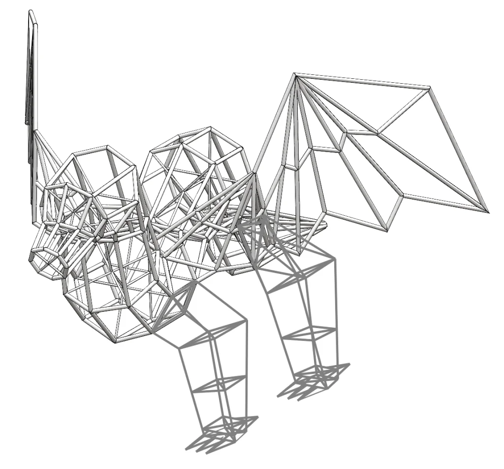
The next step is just as before – add Structural Members and Mirror.
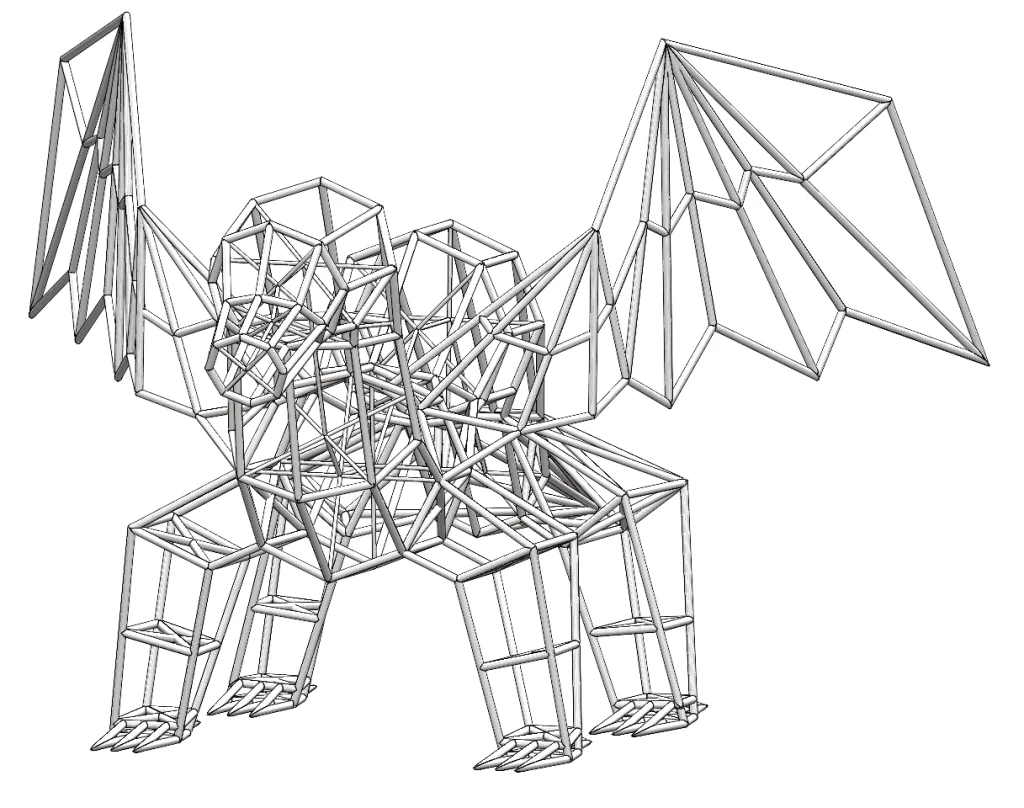
What a magnificent beast we have created! The last thing we need to do is add a beautiful bow and a hairdo. I’ll spare you the details of the hairdo –it was just the same process as before (3D Sketch > Structural Members > Mirror).
For the bow, I went with a few simple surfaces. I started by creating two circular profiles on different planes and used the Surface Loft command to create the main ribbon around the neck. Then I sketched the profile of the bow and used a Surface Extrude to create the shape of the bow, followed by a couple of quick Surface Trim commands to remove excess material.
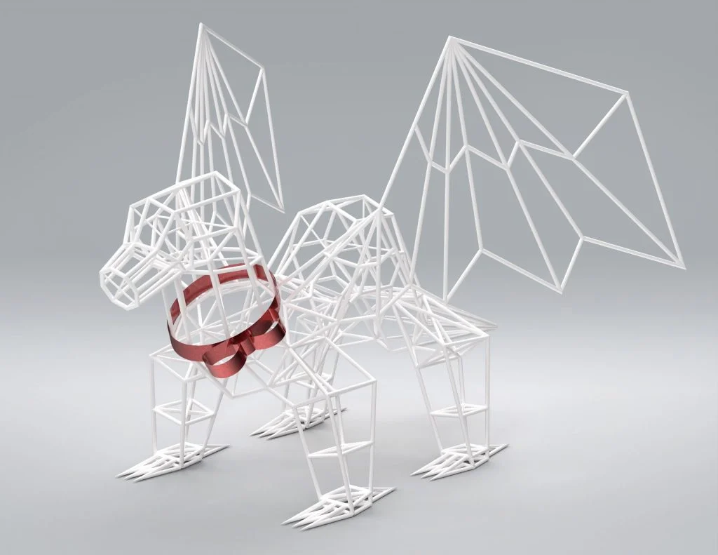

Isn’t she beautiful? She isn’t quite done, but she’s done for today. Thanks for following along! Be sure to check back for the next blog in this series to see this dragon all lit up for the holidays! Also, if you have a name suggestion for this magnificent beast, please leave it in the comments. See you next time!