
It’s that time of year again! That’s right – time to decorate for the holidays! One of my favorite traditions is driving around and looking at all of the lights, so this year I decided that I want to decorate MY house and help spread some joy of my own. To help me plan, I’ll use the power of SOLIDWORKS Electrical Professional (2D Schematics AND 3D) and then render my lit-up house in SOLIDWORKS Visualize to get a good look at the end result. Let’s get started!
As with all things SOLIDWORKS, there’s a lot of flexibility as far as where and how we want to go about designing things. I decided to start in SOLIDWORKS Electrical Schematics (SWE), move to 3D to flesh things out a bit, and then go back to my schematics to modify a few things before finishing the project in Visualize. If you’re working on a team, you can do all of this simultaneously which is super cool, but as a one lady team I also appreciate the ability to flip back and forth between programs and still have an up-to-date project on both ends in real-time. I also want to note that I’m starting with a fresh standard installation of SWE, so I will be including some custom part and symbol creation tips along the way.
Draw Schematics
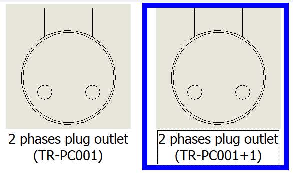
After creating a standard ANSI project in SWE, I jumped right into creating some custom symbols and components. My favorite way to do this is by copying, pasting, and modifying. In the Symbols Manager (Library > Symbols Manager) I found a standard out-of-the-box symbol called “2 phases plug outlet” (under Building > Plug outlets) and I used this as my starting point for my first symbol.
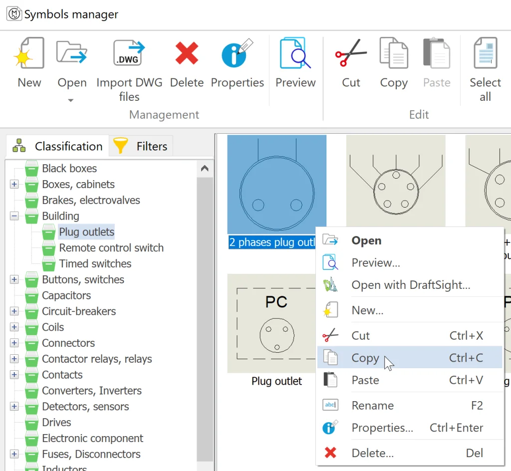
I copied and pasted it in the library and, after doing this, we see something like this:
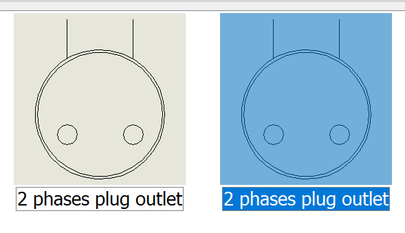
… but which one is the original and which one is new? Here’s a trick I like to use and the good news is that we only need to do it once and it will make our lives easier moving forward: modify Configuration!
At the top of the Symbols Manager, all we need to do is click Configuration and check the box next to Name before clicking Apply and OK.
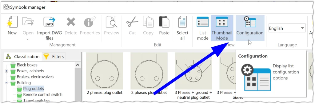
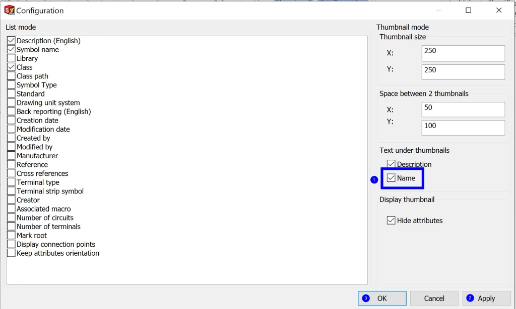
At this point, we can clearly see which of the symbols is new and which one was the original because it has a “+1” that was automatically appended to the original name, allowing us to only modify the new symbol as intended.
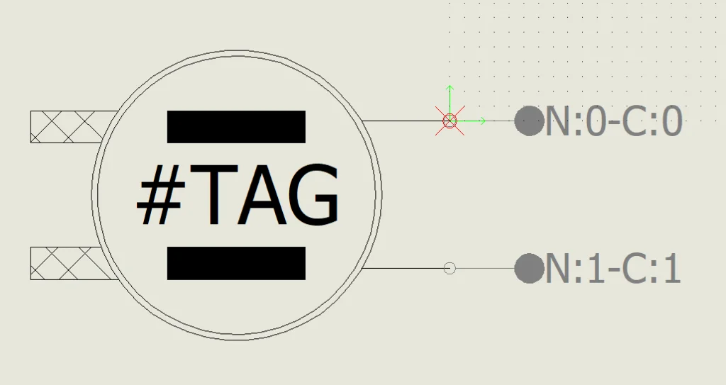
Now we can right-click this new symbol > Properties to quickly change the metadata and then double-click it to edit it. From here I quickly modified the orientation of circuits and updated some of the geometry to represent a standard stackable male plug as seen below. Then I saved and repeated the above for an LED symbol and a female plug.
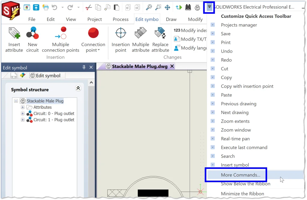
Note: The most important thing to remember when working with symbols is to make use of SNAP and OSNAP, especially when inserting circuits and the insertion point. I also like to set up keyboard shortcuts when I’m just getting started (only has to be done once per drawing type) from the little arrow at the top > More Commands… > Keyboard.
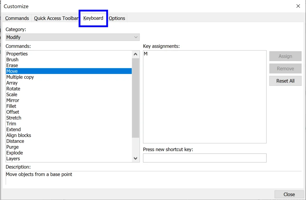
From here we can select a Category and a Command and then Assign a shortcut key (or several). A couple I like to set up immediately are Move (M) and Trim (T).
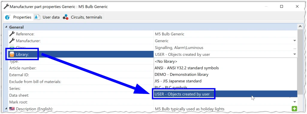
Now that our symbols are created, we can move on to making our parts. I also used the Copy/Paste and Modify method here from the Manufacturer Parts Manager, making sure that the circuits and terminals in my new parts matched the circuits and terminals in my symbols. One quick tip here – as we make new custom parts, we can put them into our own custom library, making it super simple to find them in the future. For the new parts I created, I added them all to the Library called USER.
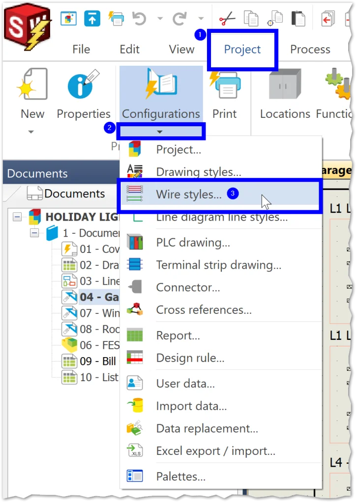
The final thing we need to customize before drawing our schematic is our Wire Styles. One way to access this is from Project > Configurations (drop-down menu) > Wire Styles…
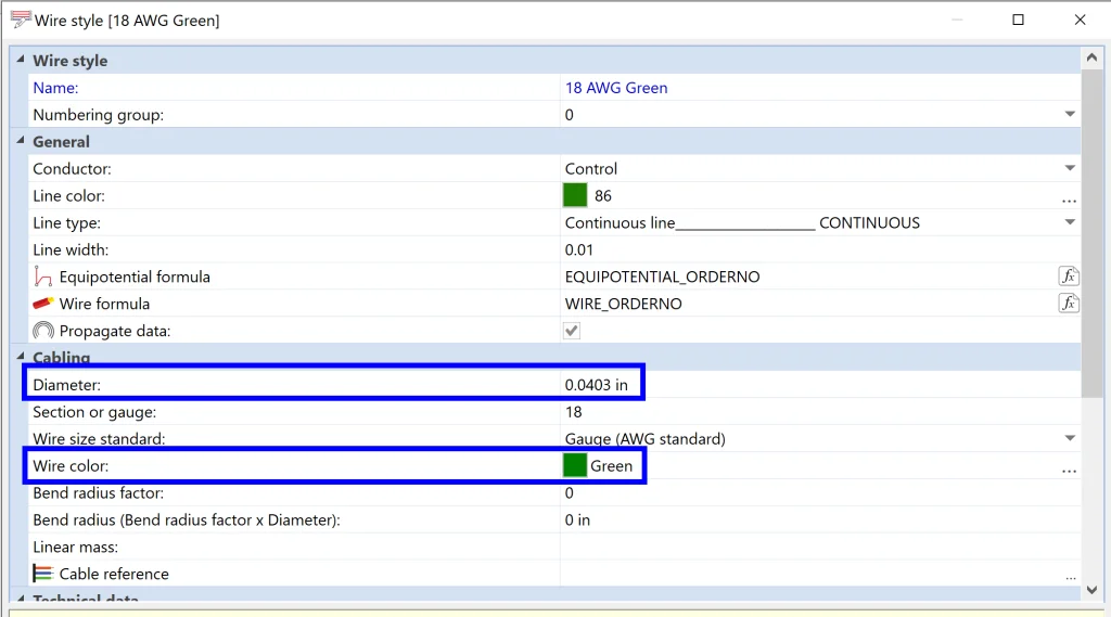
From here, I right-clicked on Group 0 – Electrical and added Single Wire Style twice before modifying the metadata to reflect both an 18 gauge and a 22 gauge green wire. Since we’re also going to add our lights in SOLIDWORKS 3D, it’s super important to fill out the Color and Diameter in the bottom section of wire metadata so that this will translate in the 3D route.
Now it’s time to draw! Setting this up took a few minutes, but the good news is that we never have to enter this information into our system again, so next time we need these custom items, we can skip straight to drawing.
I quickly drew out some light strands using the symbols and parts I made…
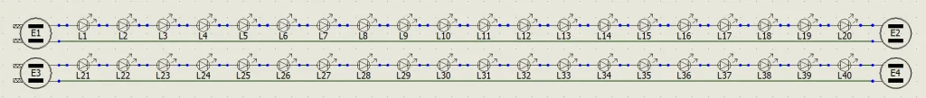
… and then created a Macro out of these elements for quick and simple design reuse by dragging and dropping these items into the Macro Palette.
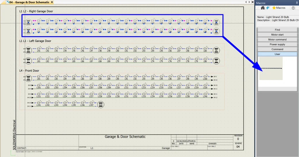
Multiple Copy was also used to reuse design elements on the same page quickly and easily. One of the things I love about this is that SWE keeps track of all of my Marks for me, something that is ESPECIALLY TEDIOUS without this level of automation. For this project, I ended up with 471 components and I didn’t have to worry about duplicating the mark for a single one!
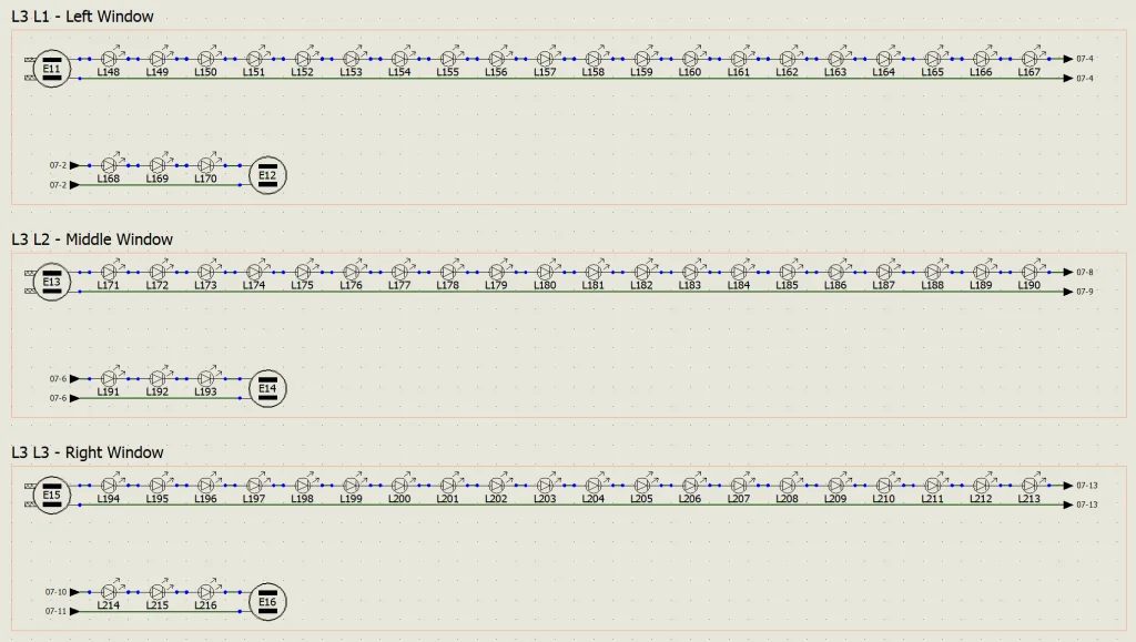
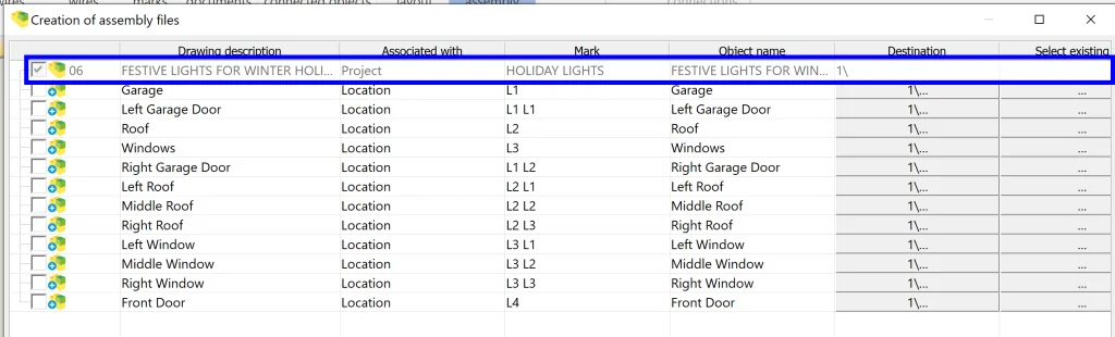
The final thing I did before jumping into 3D was assigning Locations to components using Schematic > Location Outline. This allows us to quickly organize our project and make it easy to read. For this project, I created locations based on areas of the house that I wanted to add lights to.
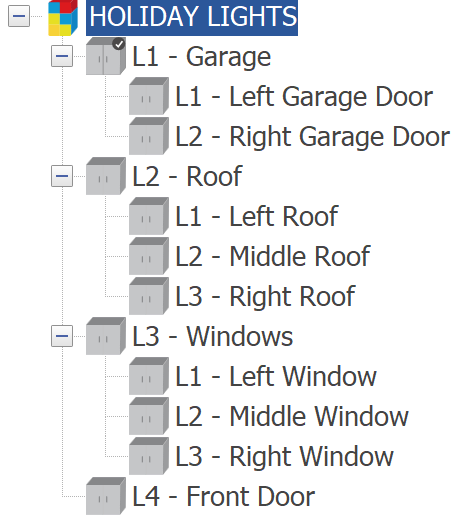
I then broke locations down into sub-locations and labeled everything in my schematics.
Model in 3D
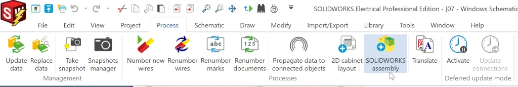
Now it’s time to switch gears and translate everything into SOLIDWORKS Electrical 3D! To create our assembly, we can go to Process > SOLIDWORKS assembly and select the locations we want to create assemblies for. In my case, I opted to just create the top-level assembly.
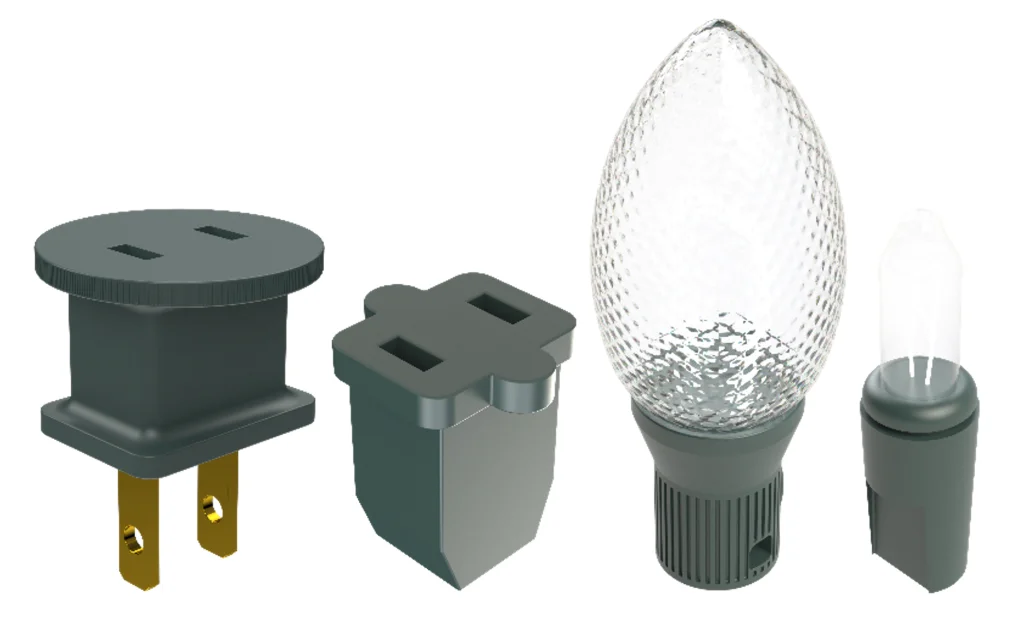
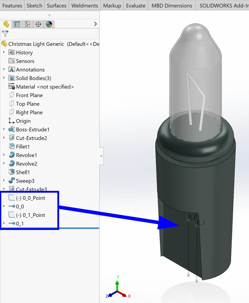
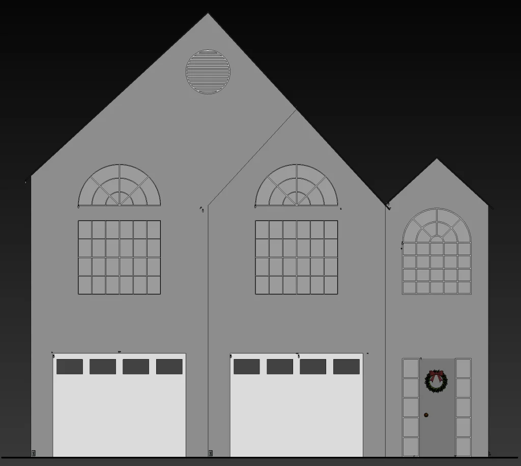
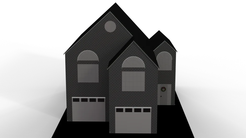
Jumping into SOLIDWORKS 3D, I started by making sure my SOLIDWORKS Electrical Add-In was activated in Tools > Add-Ins. I also activated my SOLIDWORKS Visualize Add-In since we will be using this later and started modeling by creating a simple model of the outside of my house as well as a model for the two types of bulbs we are using (C9 and C5) and the two types of plugs we are using.

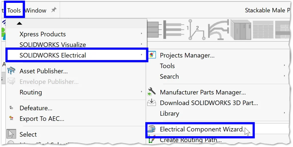
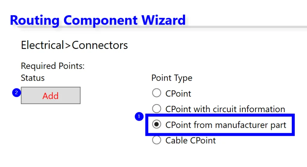
To make the plugs and bulbs smart, I went to Tools > SOLIDWORKS Electrical > Electrical Component Wizard and added connection points by manufacturer part to make sure that the circuits and terminals would match those in our 2D components.
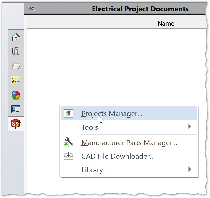
Now it’s time to put everything into our assembly and then we can wire everything up! From the SWE tab in the Task Pane, simply right-click in white space to bring up the Project Manager and open up the project. Then we can double-click on the assembly we created earlier and start adding parts!
The first part I inserted was the house itself, followed quickly by the first bulb for each section. Since I set my custom manufacturer parts up myself, I went ahead and linked them to the corresponding 3D models, allowing me to simply Right-Click > Insert from the SWE tree.

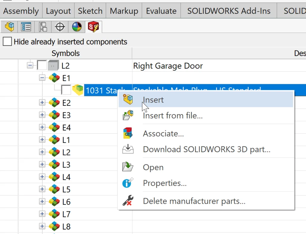
Because there were so many bulbs to place, I decided to add these in a different way. I patterned the initial bulbs and then right-clicked the corresponding SWE component from the tree > Associate.
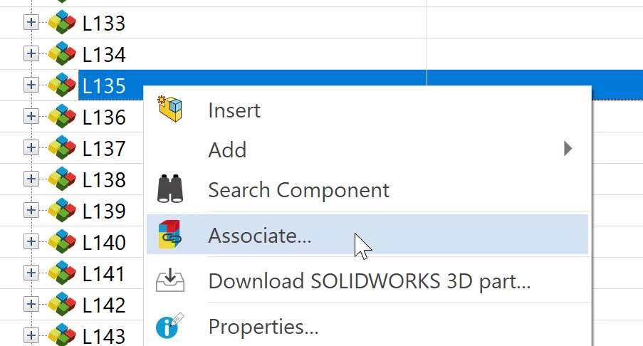
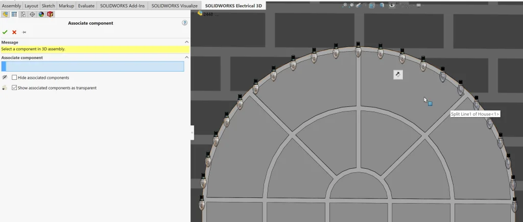
This command is especially slick because models that have already been associated with a component become transparent, making it really easy to keep track of where you are in the pattern.
Now that we’ve inserted and associated all of our components, it is time to wire everything up! There’s just one last bit of information that we can add – a 3D path that will tell SOLIDWORKS Electrical 3D approximately where we want the wires to “stick” – the EW_Path. After selecting Create Routing Path on the SOLIDWORKS Electrical tab in the command manager, I quickly sketched a routing path.
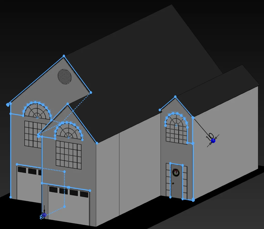
One trick here: use Tab and rotate your view as you sketch lines to make sure your path is going the direction you think it is going!
After reviewing our routing parameters, it is finally time for MAGIC (my favorite)!
When we click the checkmark, SOLIDWORKS Electrical does everything for us – routing our wires with the wire styles we specified in 2D and hooking up each component while still trying to maintain proximity to our 3D route sketch. Here’s a couple of close-ups of our wiring:
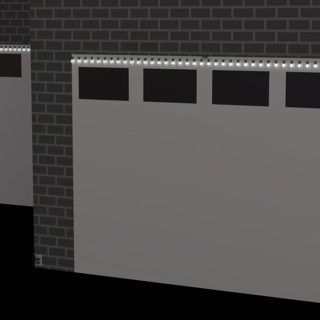
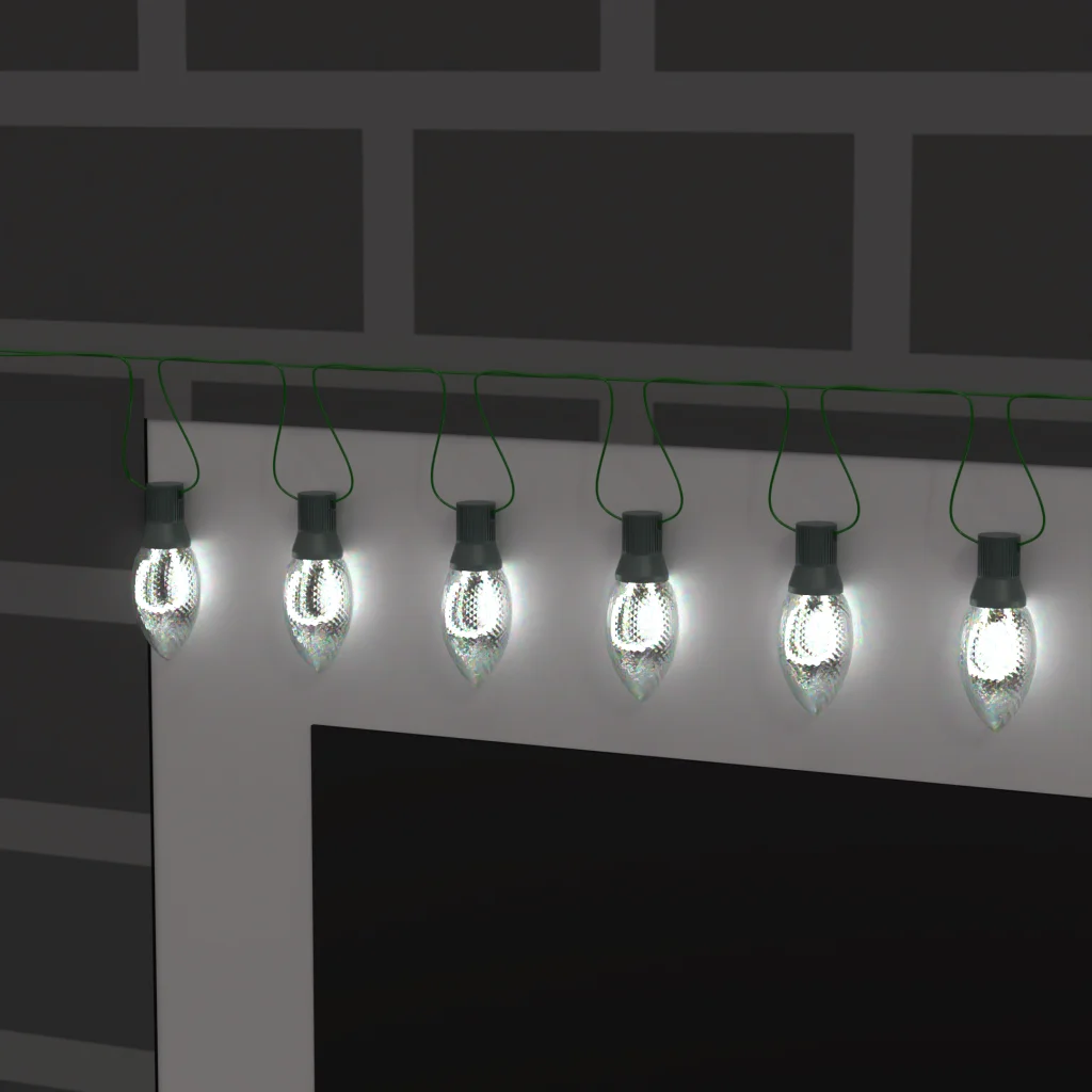
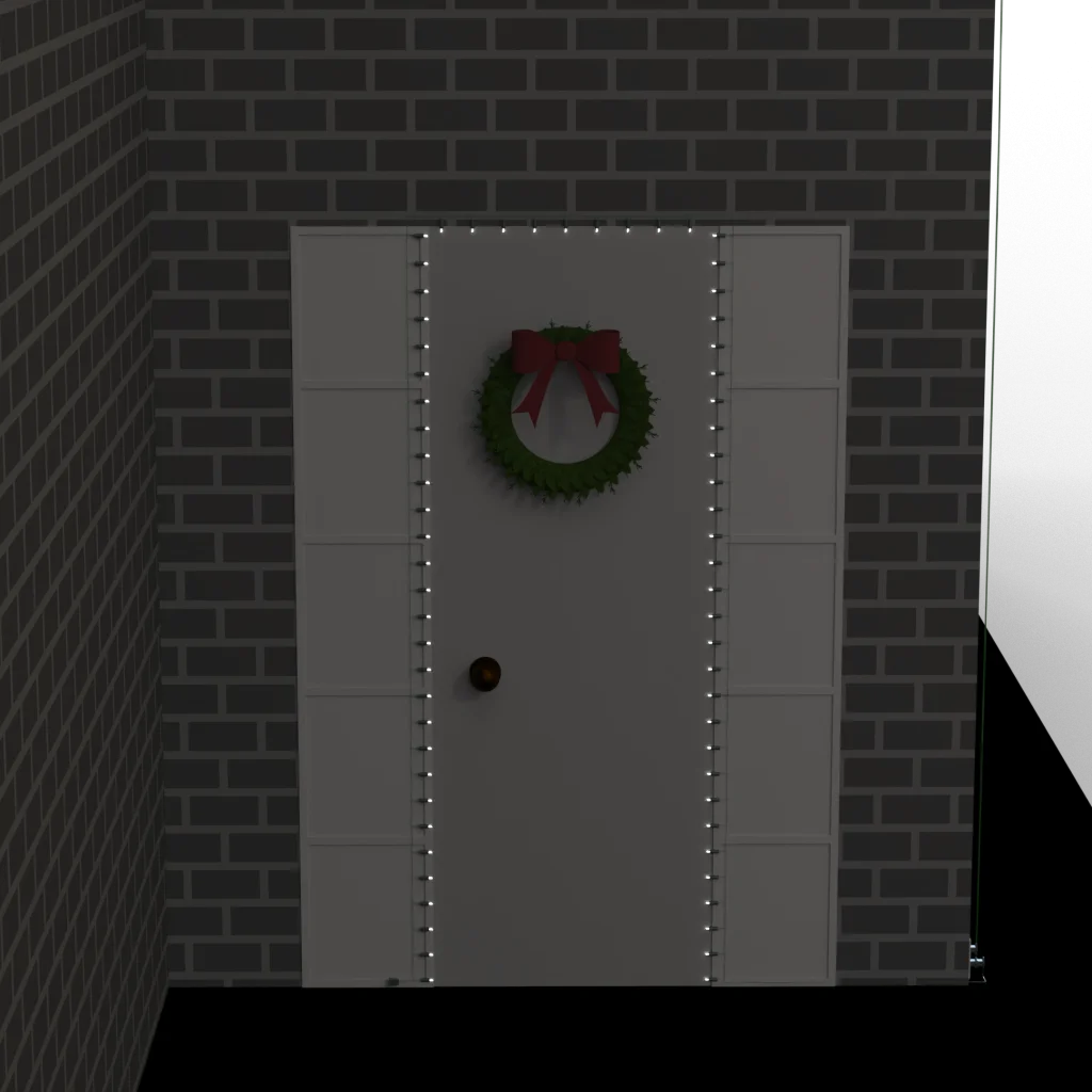
… and our finished product!
Generate Reports
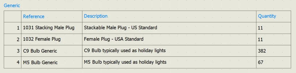
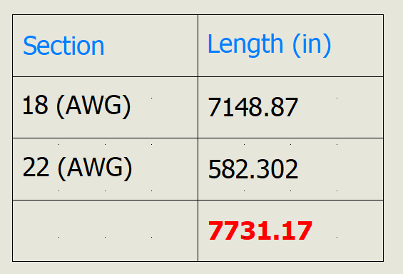
The only thing left to do is generate Reports to find our total wire length and component count. For this, we can jump back into SOLIDWORKS Electrical Schematics. From Project > Reports, I added 2 simple reports for a basic BOM and also a report for Wire Lengths by type.
BOM
List of Wires by Type
And with that… WE ARE FINISHED! Thank you so much for following along with me. I hope this brings you as much joy as it brings me and I’m looking forward to actually hanging these lights soon! If you have any questions or comments or if you want to see a blog on something specific, be sure to let me know below.
HAPPY HOLIDAYS!