The tutorial of the 4 part mold is of a ceramic beaker I designed for my Masters degree project. I used a 3d printed model to make a plaster mold from for slip casting in earthenware clay. The beaker was designed and created in SOLIDWORKS. I also used SOLIDWOKRS to see how I should create the mold, where my mold split lines would be and how best to create the mold of a complex faceted design. The beaker mold model and the cast beaker model are available to download here, you will need the beaker mold model to follow the tutorial.
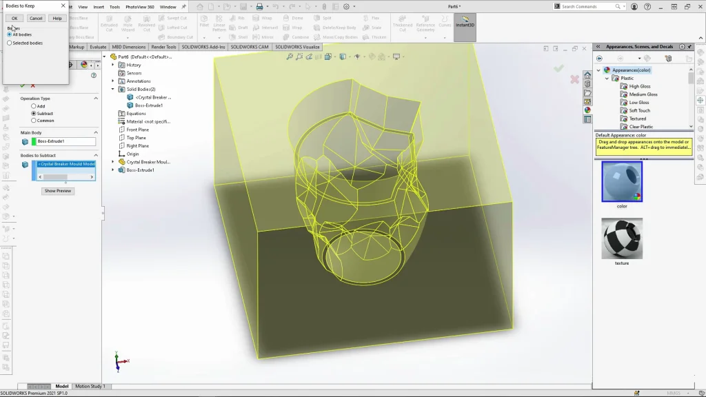
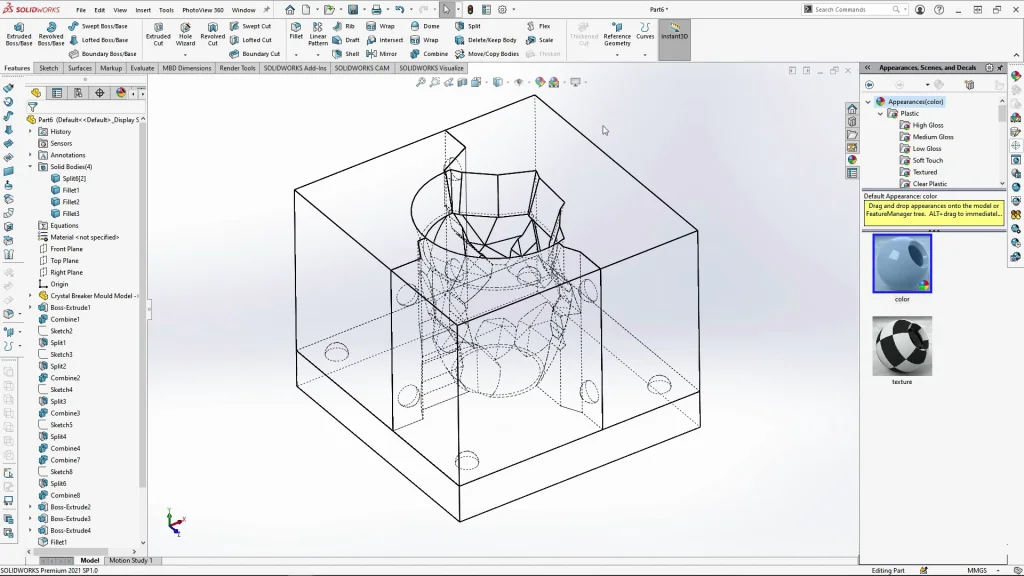
This tutorial demonstrates how the use of the split tool and combine feature can be used to create this complex mold. The tutorial begins by inserting the mold model into the part. An extrusion is made around the model but kept as a separate body. The model must then be subtracted away from the extrusion using the combine tool. This leaves us with the negative of the design within the extrusion. In this case we are also left with the negative space of the beakers foot-ring. This must be kept to combine with the base mold piece. Any ceramicist knows the importance of a foot ring, for the purpose of glazing the base without it sticking to a kiln shelf. With this feature done, we could start splitting up the extrusion into mold parts.
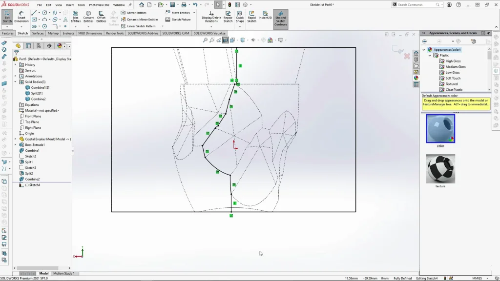
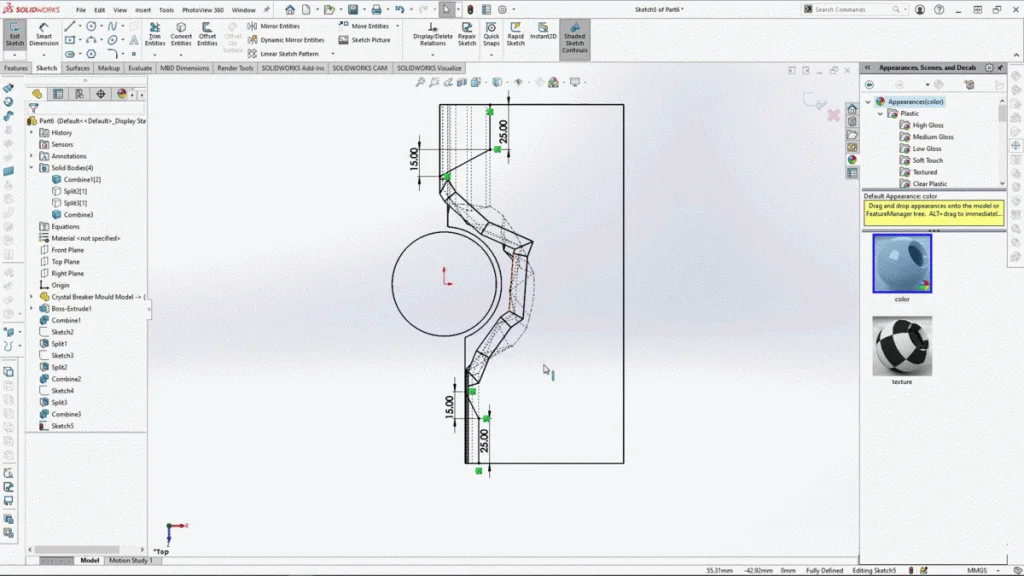
It is important when creating the split sketches that you can see exactly where model edges were. So using section view and wire view with hidden line visible is essential for creating the split lines in the right place. You can simply trace over the edges of the design. A few things to think about if you have a design that needs several mold parts like this is to ensure that where you place your split lines your design has no undercuts. It is best to analyze your mold model first to work out the best place for split lines, but to also try and use any design edges to hide mold lines on the final casting. Split lines must start from the top edge of the mold to the bottom edge otherwise the split feature will not work. As mentioned in the tutorial, you may want to pause at the split sketch parts to ensure you have followed the same split lines.
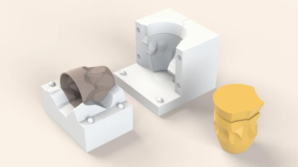
Once we have the mold split into 3 parts, you can see there is a larger part and two smaller more equal sized parts. This is normally the case for a design that has 3 split lines as the large part would be the most supporting mold piece. When removing the model, the mold would be opened with the larger piece laying on its back and the two smaller parts and base would be removed first. You can see an example of this from the actual plaster mold I produced of the design below, this makes the removal of the slip cast piece easier and safer to do.
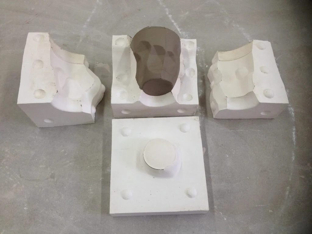
To neaten up the model and allow space to add mold natches more splits were needed. Natches are used for aligning the sections of plaster piece molds, you can see these on the image above too. Split sketches were created on each mold part, to trim away the irregular split lines. The extra bodies made from the splits were then combined onto the opposite mold parts, creating smooth surfaces for natches and neater mold split lines.
This created the flat space for natches to be added. With natches added, it was then time to start creating copies of mould bodies to combine with each other. This was so that we could create the negative spaces from the natches into opposing mold parts. I find it faster to do this way, but you could also add sketches to opposite mold parts and cut extruding/fillet in the natch holes.
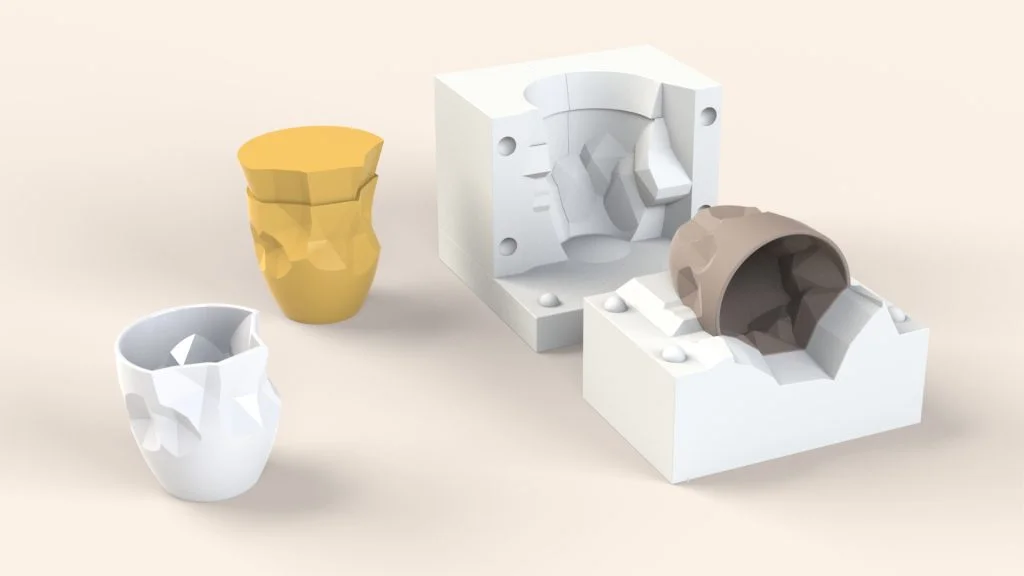
With the mold complete, I could export out individual bodies to create the below assembly and render it with SOLIDWORKS Visualize. To define the split lines for the rendering I added a small fillet along the mold edges.