In the first part of this series we recreated our broken car in SOLIDWORKS and gave it a new paint job. It turned out awesome, but our car still isn’t running, so in this blog we set out to draw a schematic for the electronics and add the components to 3D. Then we wire things up and I’ll do a quick repair on the actual car to make sure everything is working IRL. Let’s jump into SOLIDWORKS Electrical and get started with our Line Diagram.
Line Diagrams are great because they help us plan out our project and visualize it from a high level. They are also efficient because almost all the work we do now can be reused when we draw our schematic. Since this is a brand new project and I’m working off of a fresh installation of SOLIDWORKS Electrical, we can start by making some symbols.
Of course, we want to minimize the amount of work and time we put into this, so let’s create our battery symbol simply by copying and modifying an existing one.
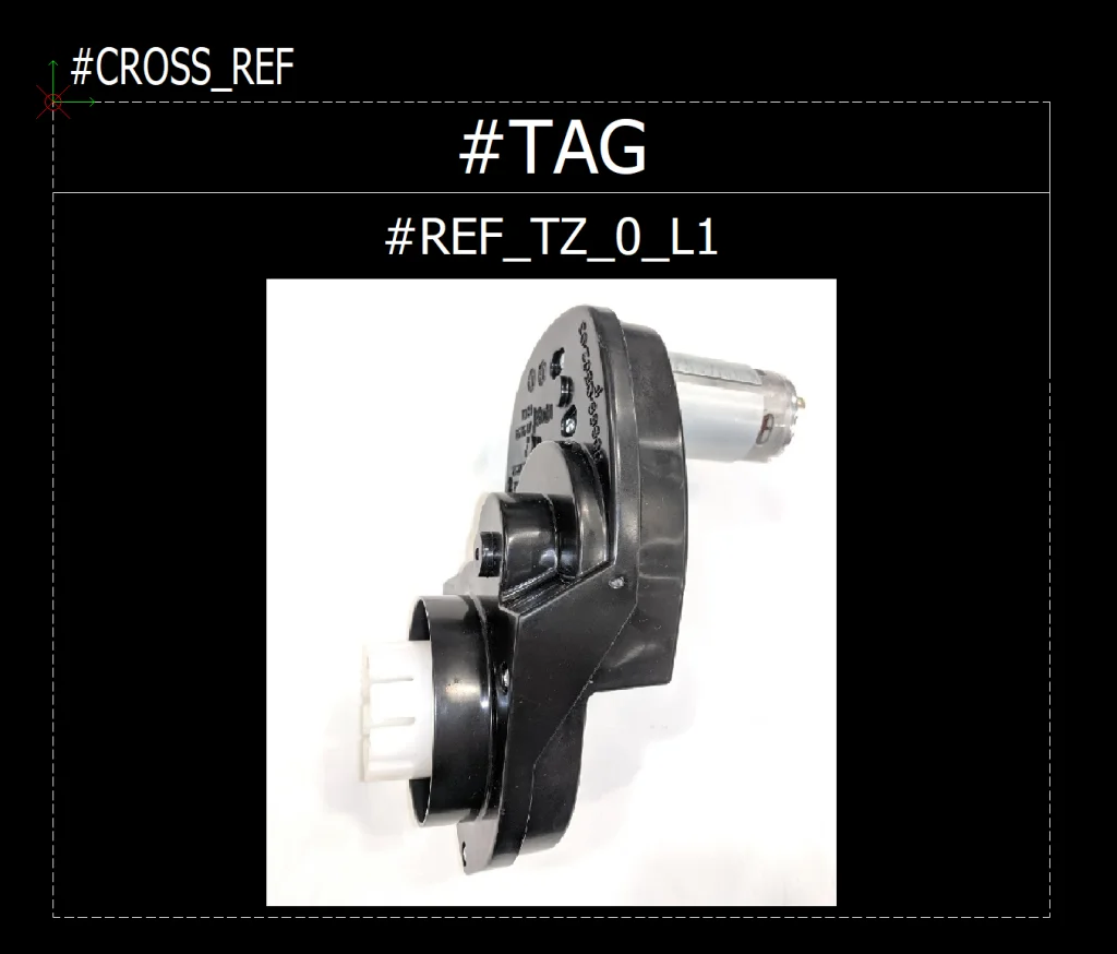
The main modification we will want to make to any Line Diagram symbol is updating the graphic, so I went ahead and got some realistic photographs of our components and saved them in .bmp format in preparation. Since most pictures don’t come in bitmap format to begin with, all we need to do is find a picture in any format, open it up in MS Paint, and go to File > Save As > BMP. This preps it for use in SOLIDWORKS Electrical.
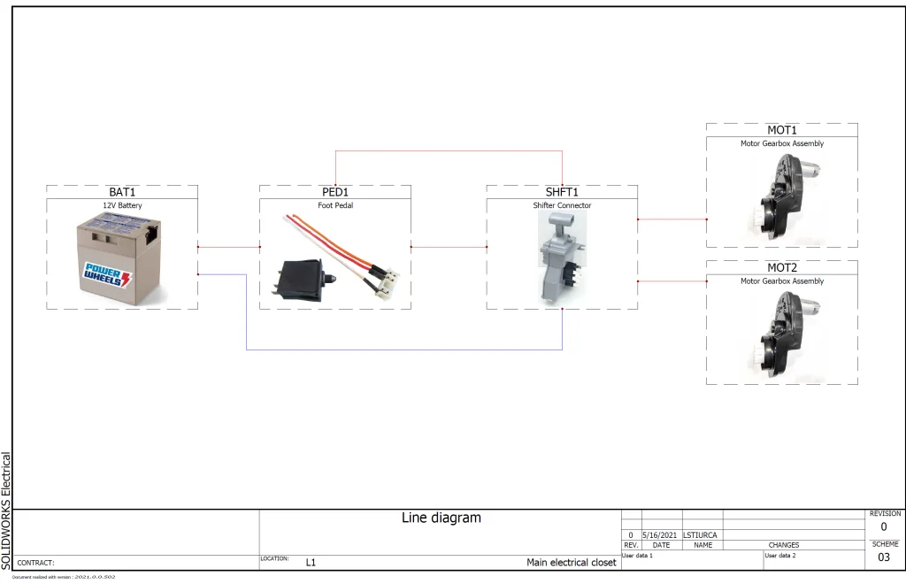
Now that we have our pictures saved, we can go to Library > Symbols Manager, find an existing symbol we like, Copy/Paste, update properties (Right-click > Properties), and double-click to modify. Literally the only thing we need to replace is the picture, so let’s delete it and then go to Draw > Insert Image to add our custom image in. Here’s what our Motor Gearbox Assembly looks like after we modify it:
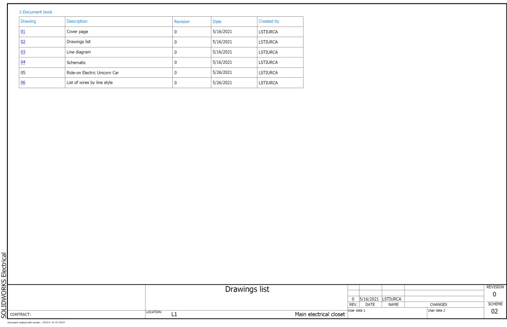
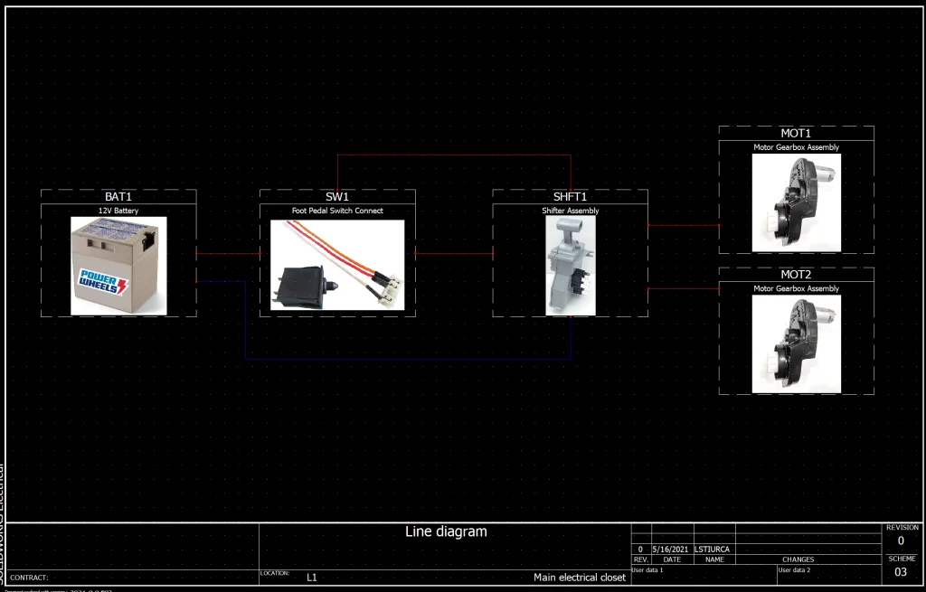
I went ahead and repeated this for 3 additional Line Diagram symbols and created some parts to go along with them, and we’re good to go! Here’s what our project looks like so far:
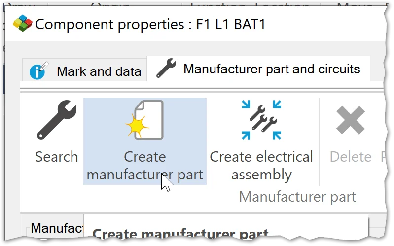
Note: Creating new parts is also easy! The way I decided to do it was from the symbol > double-click > Manufacturer part and circuits > Create manufacturer part.
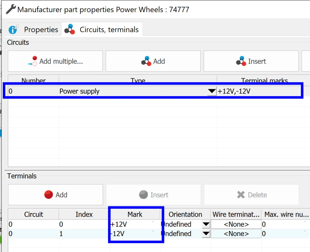
The most important thing to remember here is that our part has circuits and terminals that need to be added in addition to Reference and Manufacturer. Technically we don’t have to add them now, but remember – we get to re-use this work, so I opted to do it upfront.
Now that we’ve added all of our parts and we have a high-level overview of our project, we can do one of two things: we could continue on to draw the schematic *or* we could switch gears and create our assembly in SOLIDWORKS 3D. If there were two of me, I would do both of these things at the same time, but there’s just one of me so I decided to move to 3D for a bit and have some fun.
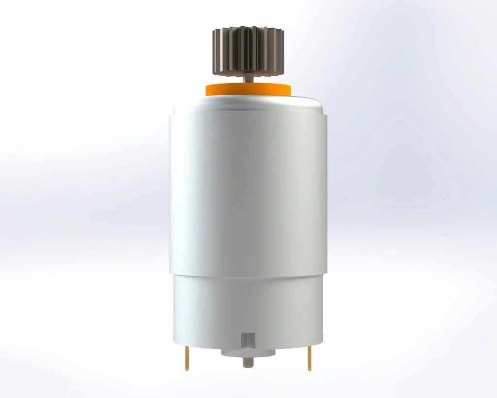
I started by creating parts for each of our electrical components that we’re going to be wiring up. This was actually quite relaxing. I just busted out my trusty digital caliper, dissected the car, and went about approximating the parts. Approximating at this stage is an art – too simple and we won’t know where the wires attach or how our parts fit in space, but too complex and we waste time. I like to err on the side of wasting time because I just enjoy the process so much, but you do you. Here’s what the finished Electric Motor looks like:
I repeated this process for the remainder of the parts and then decided to go ahead and add some electrical intelligence to my models using the Electrical Component Wizard (Tools > SOLIDWORKS Electrical > Electrical Component Wizard).
When we launch this tool, we get some pretty nifty options that simplify things significantly. For example, my favorite way of adding connection points to a model is directly from the manufacturer part (that we created earlier).
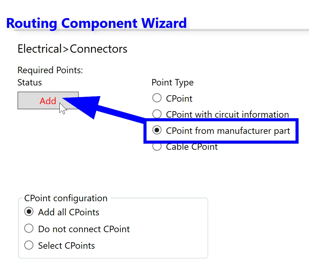
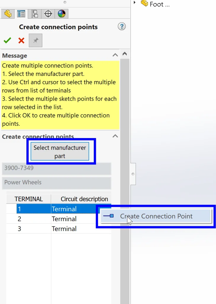
To do this, we can simply select CPoint from manufacturer part and then click Add. Next we can select our part from our library and Right-click > Create Connection Point before clicking on a sketch point (or a face in an approximate position) to create our routing point and associate it with the terminal in our actual part.
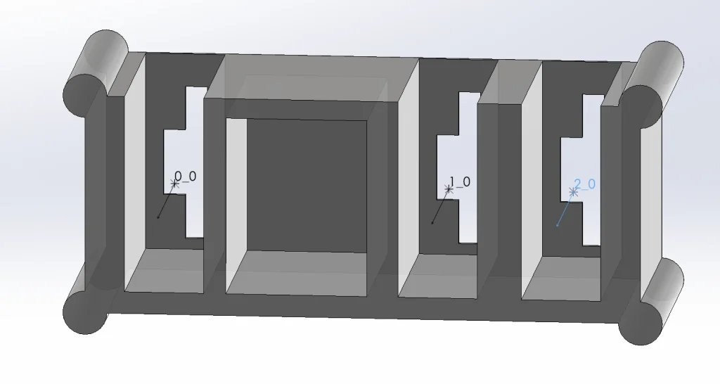
The last thing we want to make sure of is that our newly created routing points are pointing the correct direction. In this case, they are correct because they point out towards where the wires should come out of our part. If they were reversed, we could correct them quickly by finding and editing the routing point features in our FeatureManager Design Tree.
Fantastic! There are other steps we could take to simplify insertion of our models, but I decided to skip this step and save my models after just adding routing points. The next step is creating an assembly with all of our parts.
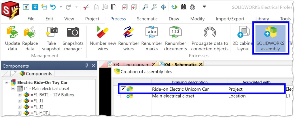
Let’s start by creating our assembly. From SOLIDWORKS Electrical 2D, we can quickly do this by going to Process > SOLIDWORKS assembly and selecting just our top Project-level assembly for creation. If this project were much bigger, I might consider splitting things up into subassemblies based on location, but this one is relatively simple, so we can do everything in one assembly without getting confused.
After creating our assembly, we can double-click it in our Document Tree to open it directly in SOLIDWORKS 3D. From here, I decided to insert all of my parts first and then Associate them to my parts in SOLIDWORKS Electrical later. This technique is also incredibly useful if you already have previously-made assemblies that you want to re-use. The only thing we want to remember here is that if we insert a fully completed assembly into our SOLIDWORKS Electrical assembly, we should dissolve it so that the subassemblies and parts are visible in our new tree. In our case, we can just start inserting components from Assembly > Insert Components. Once we have all of our components in place, the next step is super incredibly simple thanks to the power of our purpose-build tool (SOLIDWORKS Electrical 3D). All we need to do is jump over to our SOLIDWORKS Electrical tab and Right-Click on each component > Associate.
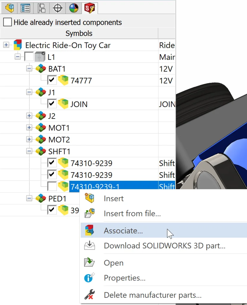
Now all we need to do is click on the 3D model that matches the part. The program helps us avoid accidentally double-associating to the same model by turning already associated 3D models transparent during this command. So simple, easy, and fast! We’re done with our work in 3D for now, so let’s jump back into SOLIDWORKS Electrical 2D and create our schematic with detailed wiring.
To start off our design, we need a symbol that represents a battery. Since SOLIDWORKS Electrical comes with a ton of pre-loaded standard symbols, we don’t need to create or even modify a symbol here. We can simply go to Schematic > Insert Symbol and select one of our Battery symbols to use out-of-the-box. Once we place our symbol, our properties box automatically pops open. From here, we can quickly Associate our symbol to the component we already created when we made our Line Diagram. Simply click on the correct component in the tree on the right and then click OK.
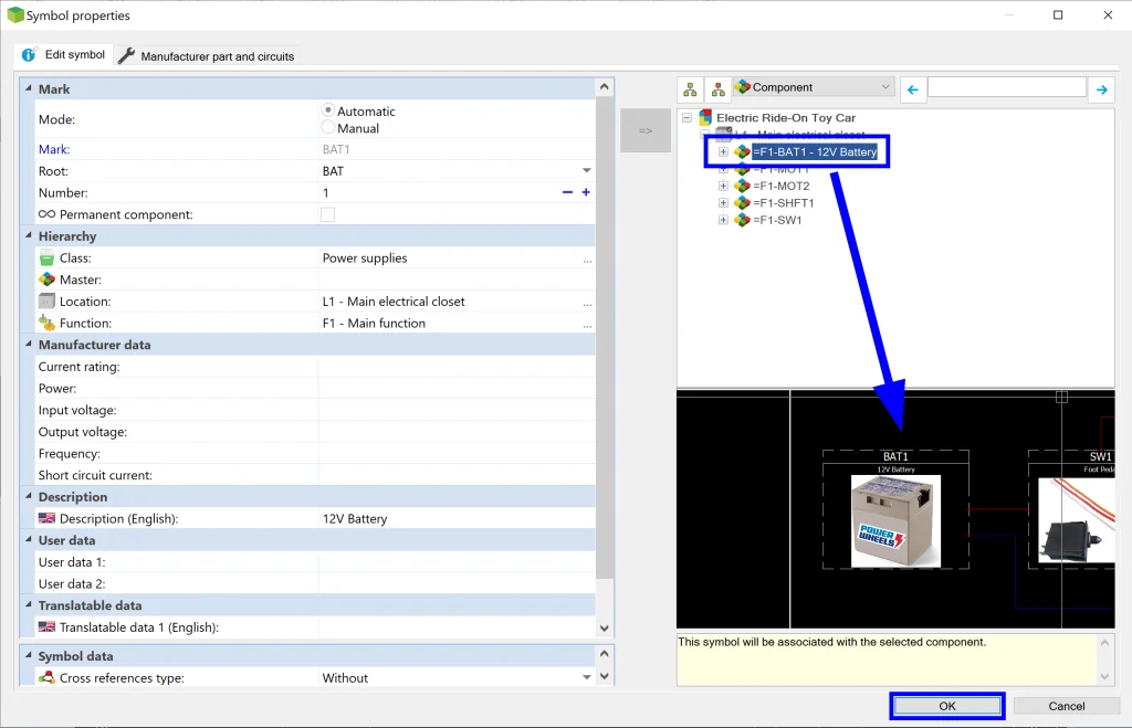
Don’t you love design re-use? The best part is that once we do this, our circuits come over as well. But wait! Since we used a symbol we didn’t create, let’s double-check them.
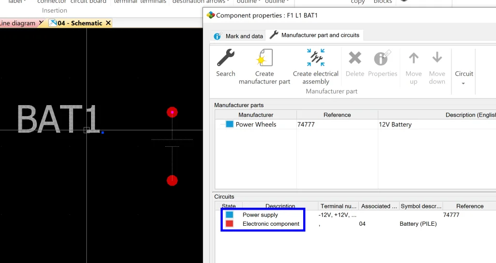
Taking a closer look, we can see that our circuit types don’t match so the circuits aren’t associating. Eek! We could solve this by modifying the circuit type in our part or by modifying the circuit type in our symbol, but I decided I was in a hurry this time, so I took a shortcut. Another way to solve this issue is simply by dragging and dropping the red onto the blue (red = circuit on the page, but not available in parts, blue = circuit available in part but not represented on the page). This forces an association and we’re good to go! Just remember to click Yes when the program points out that the circuit types are different.
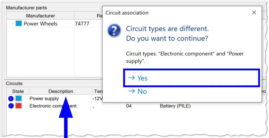
Laziness success! Of course, if we were going to do projects like this repeatedly with this part and symbol, we would want to opt for changing the circuit types, but this is a perfect solution in our situation.
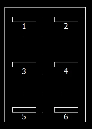
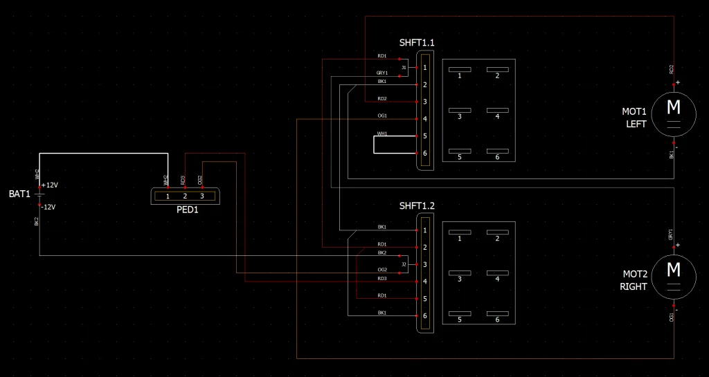
Moving on, I went ahead and used some standard connector symbols and a DC Motor symbol to complete the design. The only custom symbol I created was a simple Connection Label for the 6 pin connectors in the Shifter Assembly to clarify the layout. I did this by opening my Symbols Library and selecting to import a dxf file. From there, I made sure to specify that it was a Connection Label type of symbol and I added numbers to specify the location of terminations. Here’s the final product:
To insert, I simply right-clicked the part in the tree and selected Insert Connection Label for Components.
We’re almost done! Our last step is to create some custom wires and hook everything up.
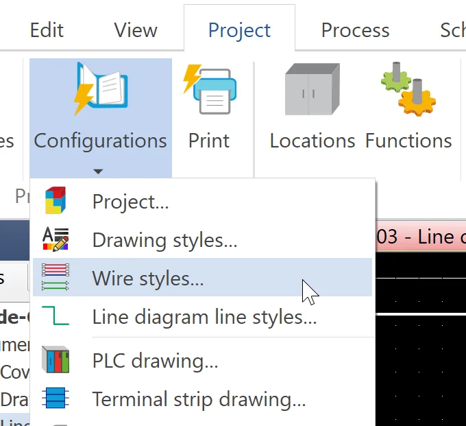
One way to access the Wire syles Manager is by going to Project > Configurations > Wire styles….
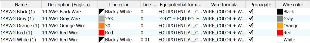
Now we can create some custom wires. Note that these wires are stored on a project level, so if we want to use them again, we will need to either create a Macro out of them or save them in our Project Template. I started by creating a new custom group and a single 14 AWG wire. Then I copy/pasted the wire four times and modified the clones so that they were all unique colors. I also modified the Equipotential Formula so that it would include the wire color since white and black wires are difficult to differentiate between in schematics. Here’s what our finished custom wire styles look like:
Now we get to wire everything up! This is incredibly simple as long as you know where everything should go AND as long as you have SNAP turned on. If you don’t have SNAP on, you can turn it on by Right-clicking in the bottom right corner or by simply hitting F9.
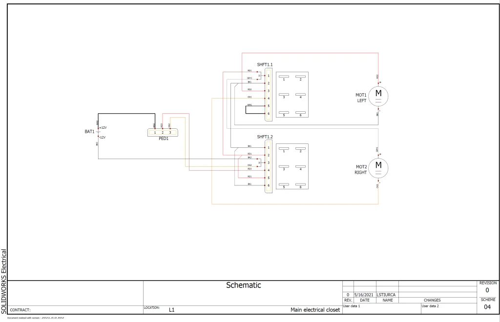
The very last step is to number our wires, so let’s go ahead and finish this step and take a look at our beautiful schematic. Simply go to Process > Number New Wires and select OK. We’re done!
Now that all of our wires are in place, we get to jump back into 3D and actually run our wires. This is probably my favorite part because it feels like magic.
Since all of our components are already placed and associated, we could technically simply click Route Wires and it should work, but it would look a bit like spaghetti, so I went ahead and gave it one more piece of information – a Routing Path to guide the wires in the correct general direction. To add one yourself, simply go to SOLIDWORKS Electrical in the Command Manager and select Create Routing Path. This opens a new 3D sketch where you can be as detailed (or not) as you like. A couple of tips for creating 3D sketches: (1) start at a point in space that is already defined such as a point on an actual face – even if you need to delete this line later, you’re better off than randomly clicking in space and (2) TAB and rotating your model are your friends – this will help you understand where your next line is in 3D space and gives you a chance to adjust by hitting tab again etc. Also, keep in mind that your routing path does NOT need to touch any of your components. It just needs to be close enough to where you want your wires to be that it ends up helping to guide them.
Here’s what our routing path looks like:

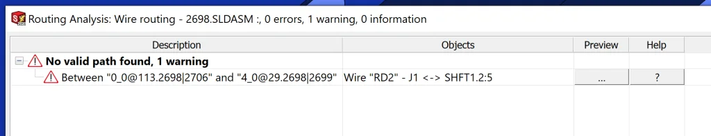
Now for the fun part! All we need to do is go to SOLIDWORKS Electrical > Route Wires and let the program do its magic. At this point, SOLIDWORKS 3D is looking at our schematic for connection information, wire color, wire diameter, and then looking back at our model for connection points and trying to route along the path we just drew all within a matter of seconds. I always like to choose the 3D Sketch option initially because it is faster and allows us to troubleshoot any potential bamboozles that pop up while routing. I also like to check the box next to Show Errors so that it’s easier to find and fix potential problems. Below, we can see that an error was detected:
Since the error specifies that No valid path [was] found, I decided to further investigate by going to SOLIDWORKS Electrical > Route Wires and selecting the Draw Graph option at the bottom of the properties dialogue box to get an idea of all possible routes. When we do this, we can see the problem clearly:
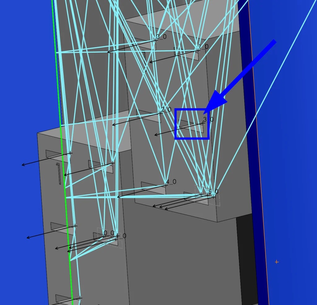
The program isn’t detecting any connection to the indicated terminal on our connector part! After zooming in, however, I also realized an even bigger mistake – my wiring was all upside down! I fixed this, rerouted, adjusted my routing path, and we’re back in business! No errors at all and everything is wired up nicely except…
Yuck! My wires aren’t following the path in this section and it’s causing an intersection. Luckily, I have an incredibly simple trick we can use that doesn’t involve re-drawing our routing path. In fact, all we need to do is edit our path sketch and insert a few Points.
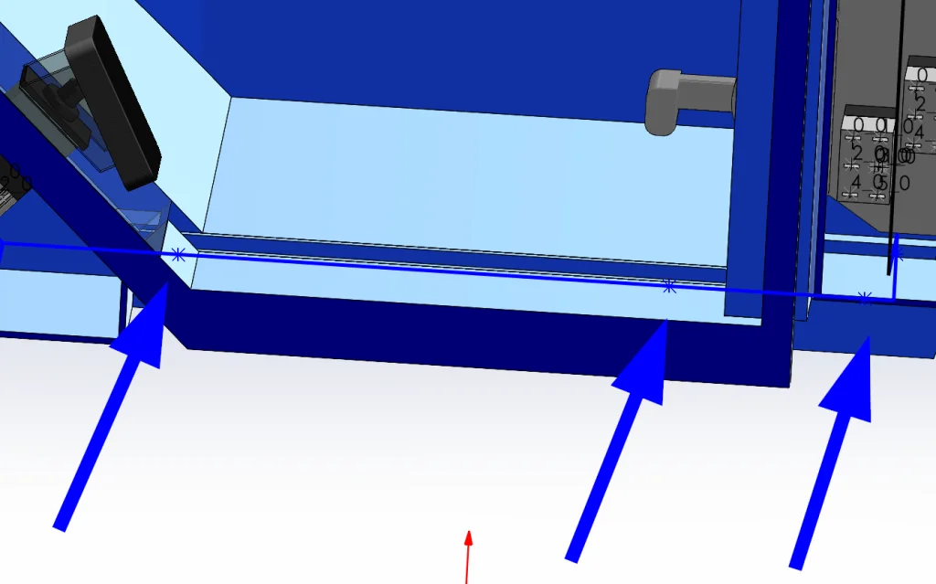
When we do this, it forces our wires to try and hit these specific points. Now all we need to do is click Route Wires one more time and…
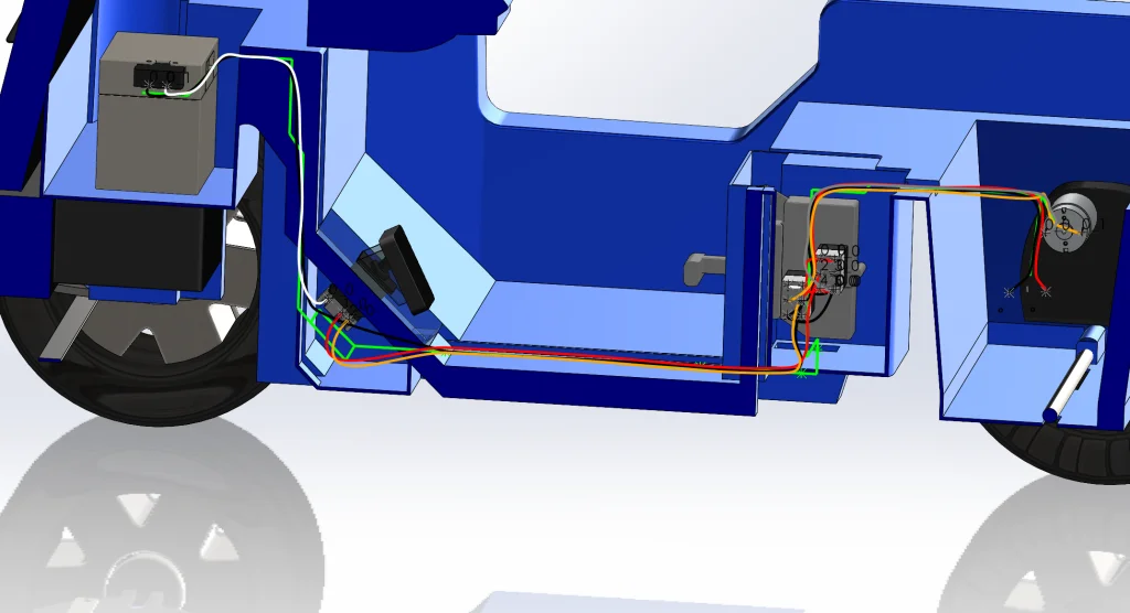
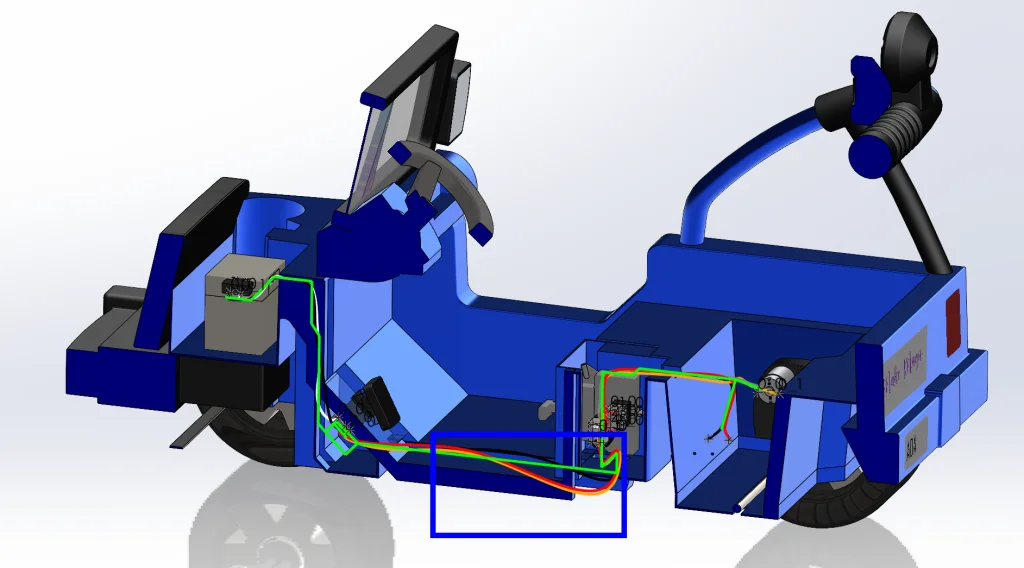
So. Much. Better! As a side note, we can also adjust our Routing Parameters or modify our Routing Path to tweak things further, but I’m happy with this result and it took two seconds, so let’s move on! At this point, we can go ahead and click Route Wires a final time but select the SOLIDWORKS Route option to get actual solid wires. I went ahead and did this and the results are beautiful.

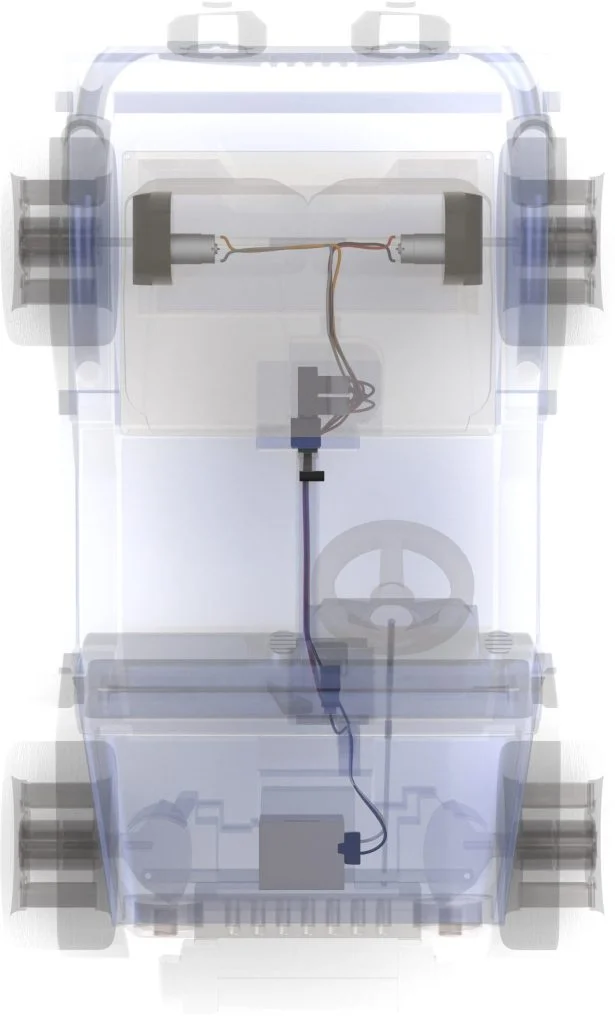
That being said, if all we’re interested in is wire length, we don’t need to take this step at all. The SOLIDWORKS Route option is great if we want to understand Duct Filing Ratio or if we are planning on rendering our work in SOLIDWORKS Visualize as I did above. Now that we have our wires routed, let’s finish everything up with a quick report so that we can fix the car!
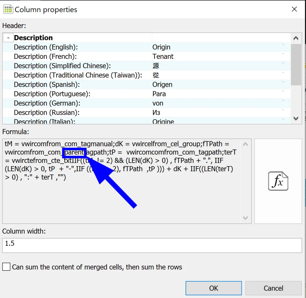
Jumping back into SOLIDWORKS Electrical 2D, all we need to do is go to Project > Reports and add the List of Wires by Line Style report from the standard reports list if it doesn’t already exist in our project. From here we can modify the report to suit our needs. I ended up modifying the formula for the From/To information so that it wouldn’t include the path of each component (F1 L1 …). To do this, all we need to do is modify the formula and add “parent” to one of the variables as can be seen below:
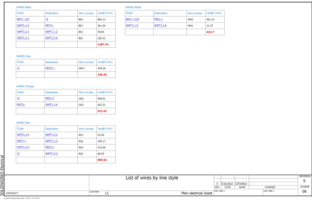
Now all we need to do is click Generate Drawings and select to create this report. When we do, we get the following fantastic reference:
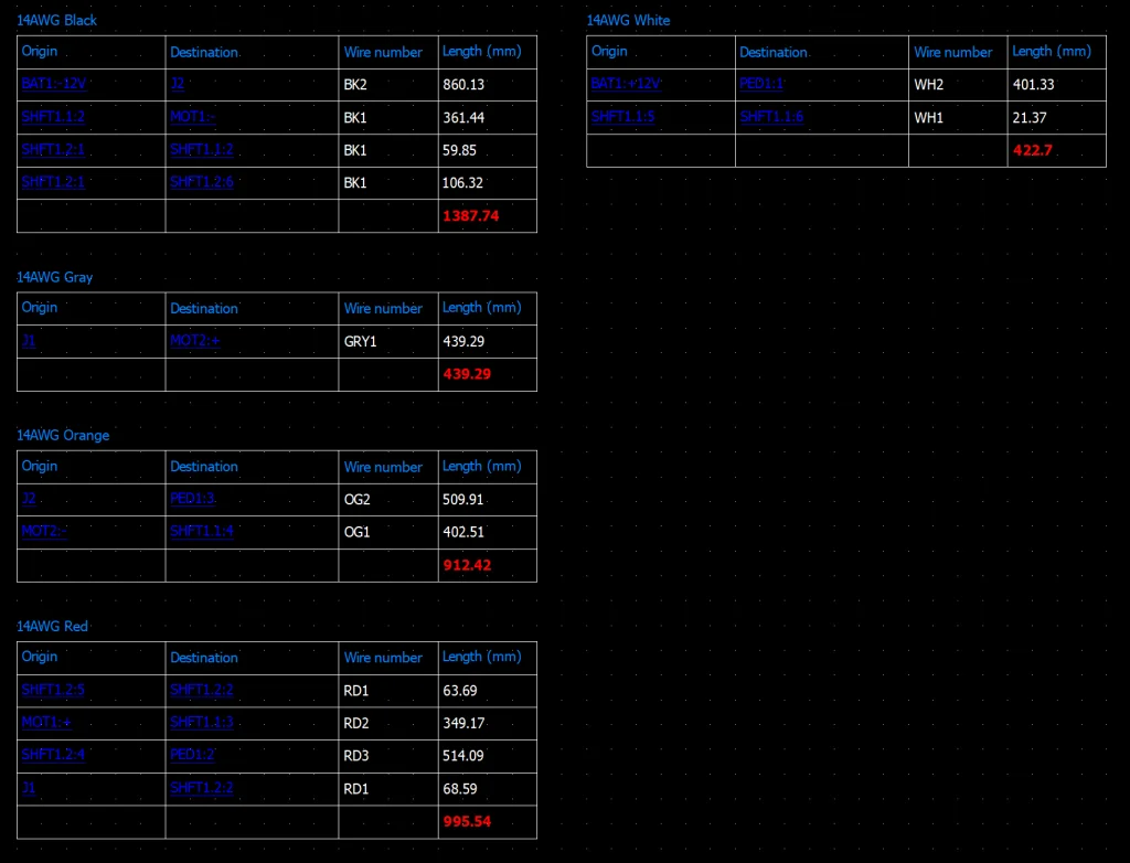
How cool is that? Now we know how much of each wire type we need and we can even pre-cut our wires if we want to. Another trick I like to use in the report is to modify the Length formula to include 10% more wire than what was routed. This gives manufacturing a built-in safety net.
The final thing I did was export my project to PDF by going to Import/Export > Export PDF Files. I absolutely LOVE the PDFs we can get from this program. I’ve noticed more and more companies are switching to having tablets or computers with large screens on the manufacturing floor as an eco-friendly solution, but also these PDFs are so easy to navigate because of all the hyperlinks that are automatically inserted for us. For example, if we click on MOT1 in our Line Diagram, the PDF will jump to the representation of this motor in the Schematic. There are also hyperlinks in our reports that can help us navigate and understand our project quickly and simply. Here’s what our PDF looks like once exported:
We’re done! Thanks so much for following along. In our next blog we will revise our work and create a SUPERCAR version of this ride-on electric car, so be sure to check back in soon! As always, feel free to share and comment below if you have any questions or if you have an idea for something you would like to see in the future. Bye for now!