

When I was a kid I dreamed of someday having my very own electric car, so as a grown adult with a toddler, I decided that my daughter NEEDS one. Recently, I was browsing our local Buy Nothing group and I found an absolute jackpot – a FREE electric car. Two seats, four wheels, and… oh yeah, it doesn’t run. Details, details, right? We can fix broken things! We are engineers! We picked the potentially functional car up and, after taking a couple of measurements with my multimeter, I determined that the issue was the electric motor – NBD, as they say. The only other issue was the paint job – it could use an upgrade.
So… in this blog and in the following two blogs, we set out to (1) recreate the car in SOLIDWORKS and give it a new paint job, (2) draw a schematic for the electronics and add the components to 3D, and (3) give the car an upgrade (MAKE IT GO FASTER) but modifying the electrical components and giving it a pair of new wheels. Let’s get started with the mechanical bits.
Step 1: Get orthogonal pictures of the model vehicle.
This is really important because these pictures are going to be our reference. If they aren’t orthogonal, the points on the side view won’t match up with the points on the top view, no matter how much image manipulation we do.
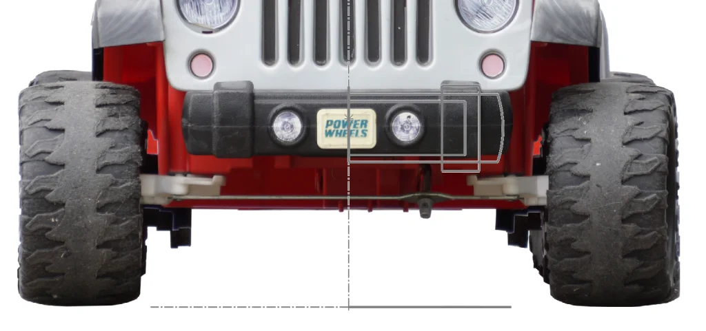
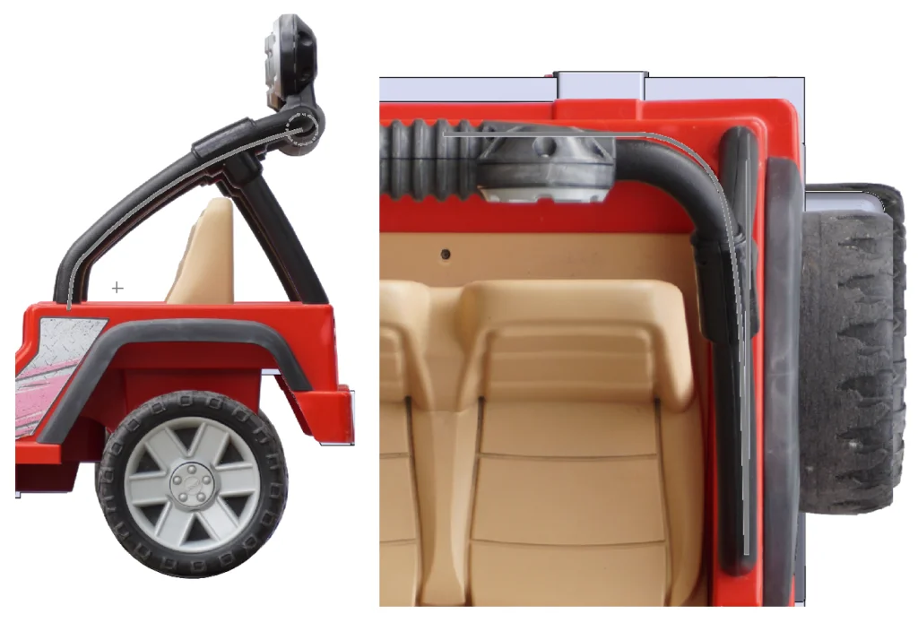
That being said, with all of the cameras and technology that we have at our fingertips today, this should be easy, right? Errrrr… turns out not-so-much. Well, I suppose it depends on your circumstances. I’ll show you a picture to explain mine:

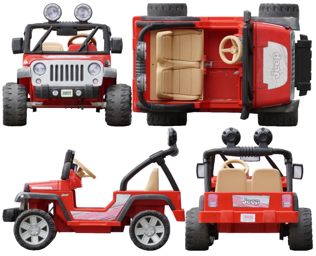
Without distraction or interruption, however, the technique is quite simple. All you need to do is take a zoomed-in picture from as far away as possible. This imitates an orthogonal lens and, at least in my case, is the closest I can get. I also recommend taking these pictures during daylight hours unless you have a well-lit house and a long corridor. I learned this the hard way so that you don’t have to! I made sure to get TOP, BOTTOM, FRONT, BACK, LEFT, and RIGHT images, but technically that’s a bit overkill for this project since there is a lot of symmetry in this model.
Step 2: Rotate, Crop, and edit.
The first two steps are necessary in order to make sure the pictures will line up, and the “edit” step is a trick I use – I like to remove the background to make it even easier to line my pictures up. This also helps me because I really zoom in and I can find the imperfections/non-orthogonal bits of my pictures as I go. Like I said earlier, the pictures are close, but not perfect. You can use any photo editing app to do this as long as you have the ability to Rotate, Crop, and Remove Background. I like to use GIMP because it is free and it even allows you to crop directly to content after you remove the background, but my husband swears by photopea.com which is also free and doesn’t require an installation. Here are some of the photos I collected and edited:
We’re off to a good start! Now the fun part – we get to open SOLIDWORKS!
Step 3: Add your pictures to a new SOLIDWORKS part.
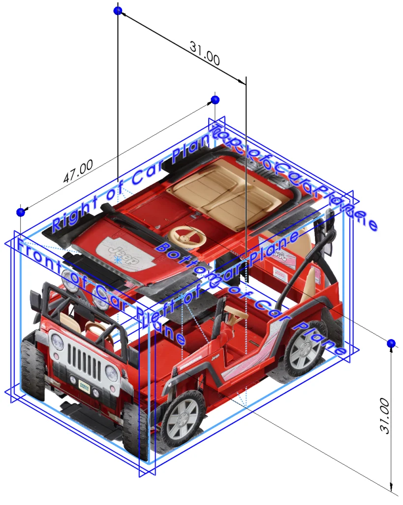
Take a few measurements and add your pictures to your SOLIDWORKS model, being sure to scale as you go. A trick I used here was to create a 3D sketch first with a “cage” around the exterior measurements that I took. This made it easy to visualize where each picture should be. I also created planes for each sketch picture to match and inserted my pictures directly onto these planes (Tools > Sketch Tools > Sketch Picture). The simplest way to scale these pictures is to set the Width or Height in the properties box and move them using the X and Y positioning boxes.
Here’s what it looks like so far:
Off to a good start! Now let’s get to modeling.
Step 4: Choose a place to start and dig in.
This is the second-to-last step, but it is a big one. My goal in this next section is to step through most of the techniques used to finish the mechanical design using the reference pictures. If I attempted to step through every single thing, you would be reading a chapter book, so I won’t do that. You’re welcome. However, if you do want more details about any of it, feel free to comment below or send me a message on LinkedIn.
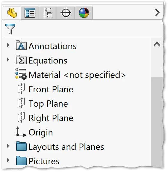
Because we have so many perfectly imperfect photos, it is important to pick one or two as your “default” – as in, if things aren’t matching up, you know where to go. I chose the LEFT side view as my default and FRONT as my backup for most things. Another tip before we dig in to the nitty-gritty is to organize features into folders in your FeatureManager Design Tree. This is a good idea for any model that is going to have a large number of features because it allows you to quickly edit specific sections as needed without looking through a thousand features first. Also, for the reference pictures specifically, it allows you to very quickly turn them on/off by suppressing the Folder itself rather than having to find and Shift + Select the group of sketches. For reference, here’s what our FeatureManager Design Tree looks like so far:
The first part of the car we are going to work on is the hood and the technique I used here involves surfacing. Many moons ago I recreated a Delorean using 99% surfacing, so I figured this would be a fun way to start things off.
We’re going to create a Surface Loft, so we need two sketches. Looking at our LEFT side view, we can see that these sketches will need to be on non-default planes, so let’s create those first. Sketching on the Right plane, I created two lines representing the start and end of our loft.
From here, I selected the lines individually and used the shortcut key (S) to select the Plane feature. The first reference is the line and the second reference is a plane – in this case we can select the RIGHT plane and make sure to select the Perpendicular relation.
I repeated this for the second plane before switching to a FRONT view and opening a sketch on the plane we just created that is closer to the front (I renamed this to “Grill Plane” in my tree for the sake of organization and sanity). Now we get to trace the front of the hood! Note: it is important here to trace our reference picture in a FRONT view rather than in a view normal to the angled sketch plane that we just created. I tend to personally gravitate towards using lines and arcs here instead of splines, but you could use splines just as easily. Here’s what my trace looks like:
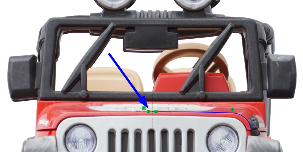
Another trick to use here is to take advantage of symmetry. I only traced half of the vehicle, making sure to add a tangent relationship to a horizontal construction line at the middle so that, once mirrored, the surface would look smooth. From here, we can use the Surface Loft command, selecting the two sketches we made to loft between and then Thicken them, using the FRONT view as a reference for how much to thicken them. At this point, I realized the fatal flaw in this technique: our front and back edges end up being curved.
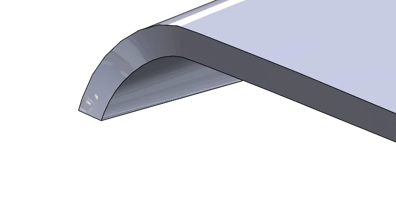
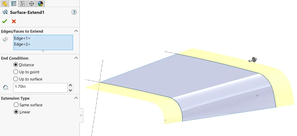
I could have gone back and finished tracing/creating sketches that would have allowed me to do a normal loft, but at this point, I was committed to the technique, so I went back and added a few steps to correct this. First, I rolled back in my tree to right after the surface was created and used Surface Extend to create a larger surface than needed.
Then I rolled back to the end (after thickening) and used the Cut with Surface command, along with the two planes we originally created, to cut away the extra. This leaves us with two beautiful planar faces at the start and end of our hood. Here’s what the hood looks like after applying Mirror to the half we created:
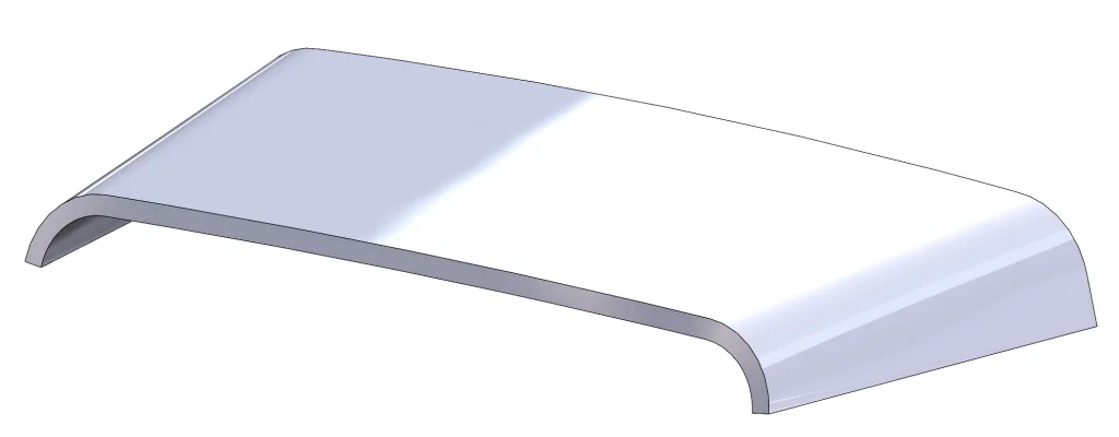
Way better! Now all that’s left to complete this feature is to add a couple of fillets, although we can easily leave this as the last step in modeling (this is often advantageous, but in this case, it is fine to add them now). Either way, it’s all good in the hood.
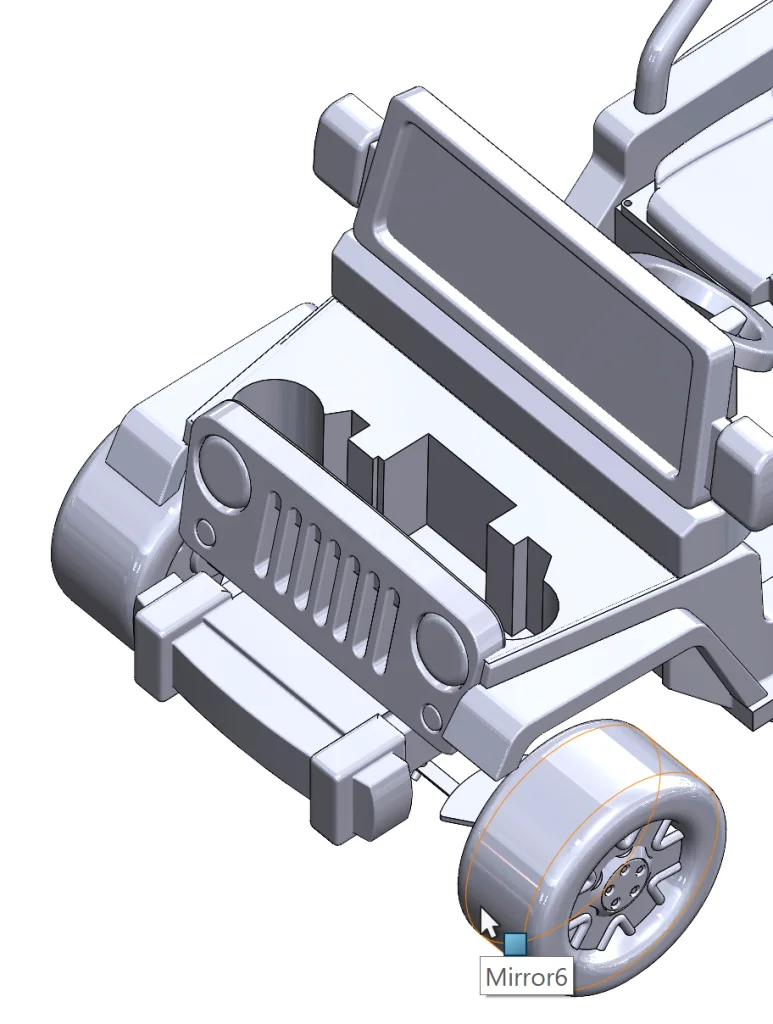
The next portion of the car I modeled was the grill, but I used simple extrudes and cuts here, so let’s move on to the front bumper.
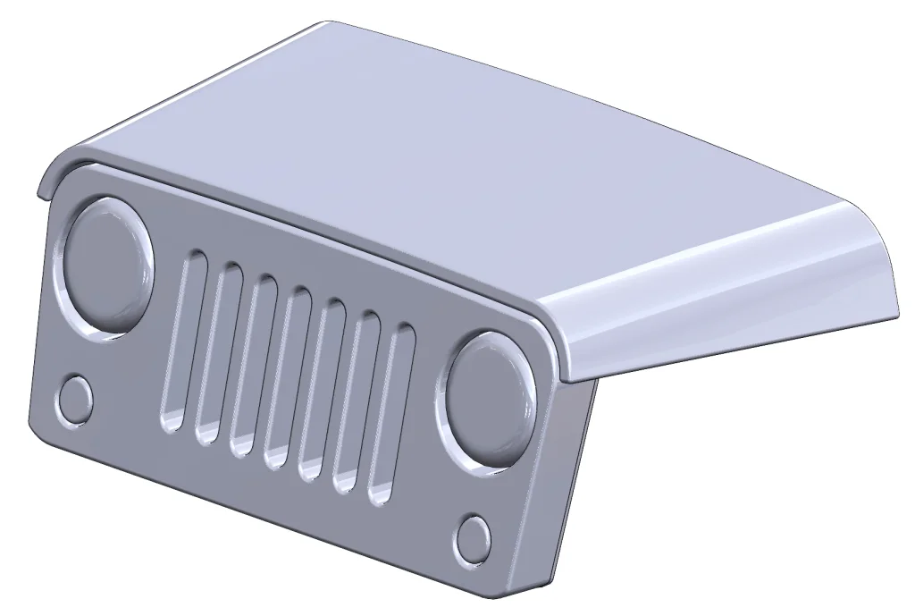
The technique I used here involves the massively useful Intersect command. We begin this technique by sketching the basic shapes we see in the bumper from the TOP and FRONT views. I sketched these on the default TOP and FRONT planes.
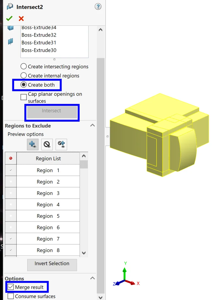
Now we extrude each shape out past the point where the material actually exists, making sure to un-check the Merge box in each feature. We get this crazy thing. Don’t panic – it will get better, I promise!
Now it is time to activate the magical Intersect command. After activating the command, we want to select all of the bodies we just created and click the Intersect button after selecting Create both in the properties box. Then we can start clicking in the graphics area to remove excess material. I find this to be the simplest way of getting exactly what I want, especially with a large number of bodies, but we could have also checked and unchecked boxes in the Regions to Exclude area of the properties box. Once we have exactly what we want, we can select Merge result and hit ok.
Now all that’s left is to Mirror our body on the RIGHT plane, add a quick Extrude for the connector (traced from the BOTTOM reference picture), and add some fillets to get rid of sharp edges.
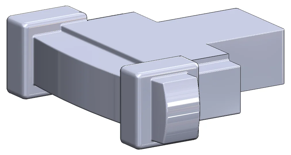
Beautiful and fairly simple really, considering all of the shapes we created with a single command!
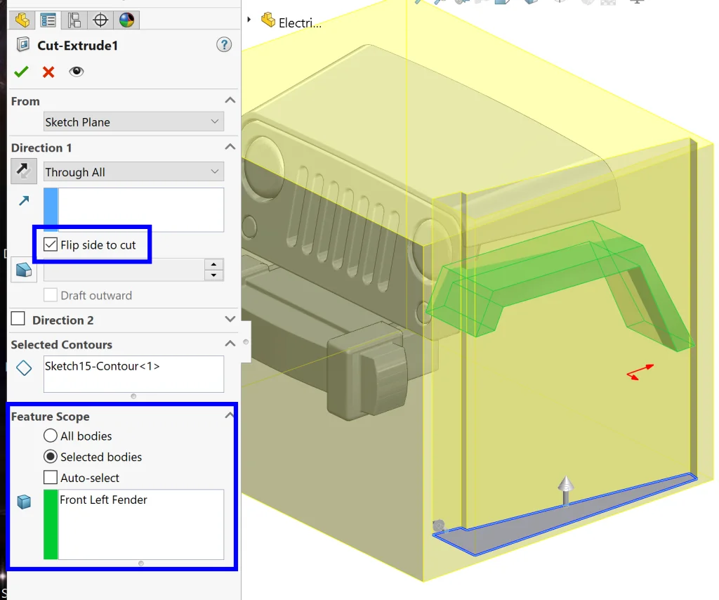
The next part of the car I decided to tackle was the front fender. I could have used the Intersect technique again, but because it was so simple I decided to just use the Extrude and then Cut-Extrude technique here. From the LEFT side, I traced the profile and used the Extrude command to draw out a solid close to the correct size.
From here, I traced the profile from the TOP, and cut away the excess material using a Cut-Extrude by selecting Flip side to cut in the command and selecting the body we just created under Feature Scope.
Next, I added a couple of fillets to match the original side profile before running into an issue! Due to the imperfectness of our pictures, the profiles didn’t line up correctly, resulting in an unwanted flat face at the front.
Yikes! Luckily, this is a super easy fix. All we have to do is right-click on the face and go to Delete Face, being sure to select Delete and Patch in the properties box.
Instant fix! Now, all we need to do is add a couple of fillets, Mirror our body, and move on to the next feature.
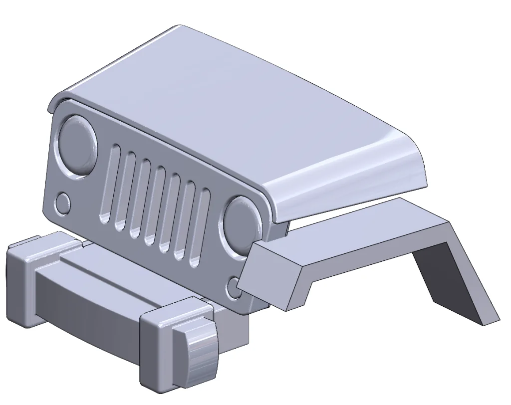
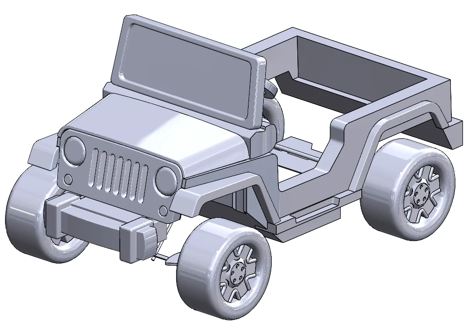
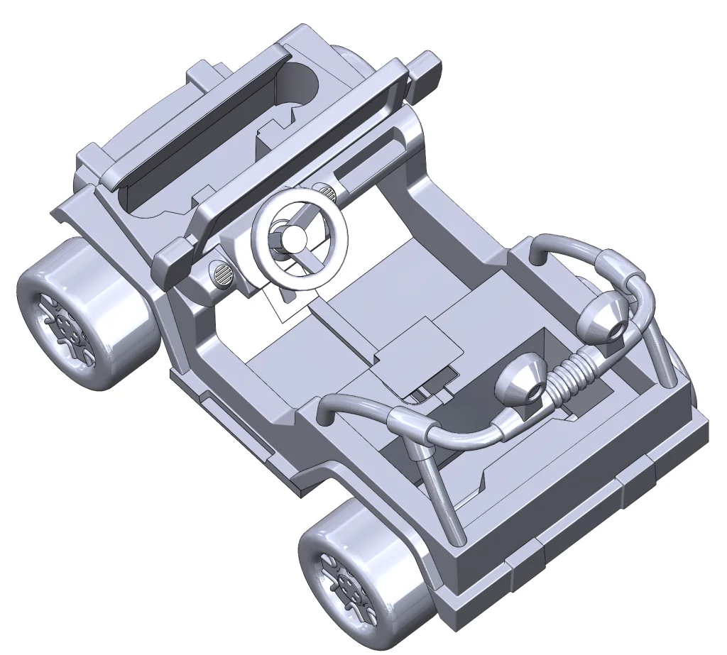
At this point, I basically used the techniques we discussed above to create a bunch more geometry – wheels, the windshield, the side panel, the dash, steering wheel, side step, floor, front axle, back axle, back bumper, and the back panel/bumper were all fairly straightforward with few new techniques of note, so let’s fast forward a bit to the floodlights because these are a bit more interesting. Just to catch you up, here’s our model so far:
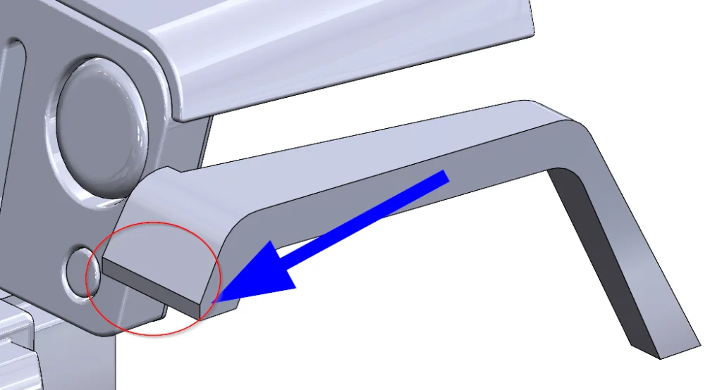
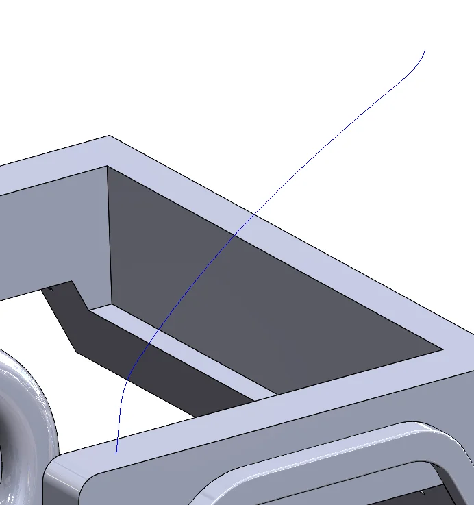
For the support portion of the floodlights, I started by tracing the profile for the first segment from the LEFT side view and then from the TOP view (modified slightly so that things line up later) like so:
Then I selected the sketches and used the Project Curve command to project the first sketch onto the second sketch, essentially defining their intersection. Here’s what the resulting curve looks like:
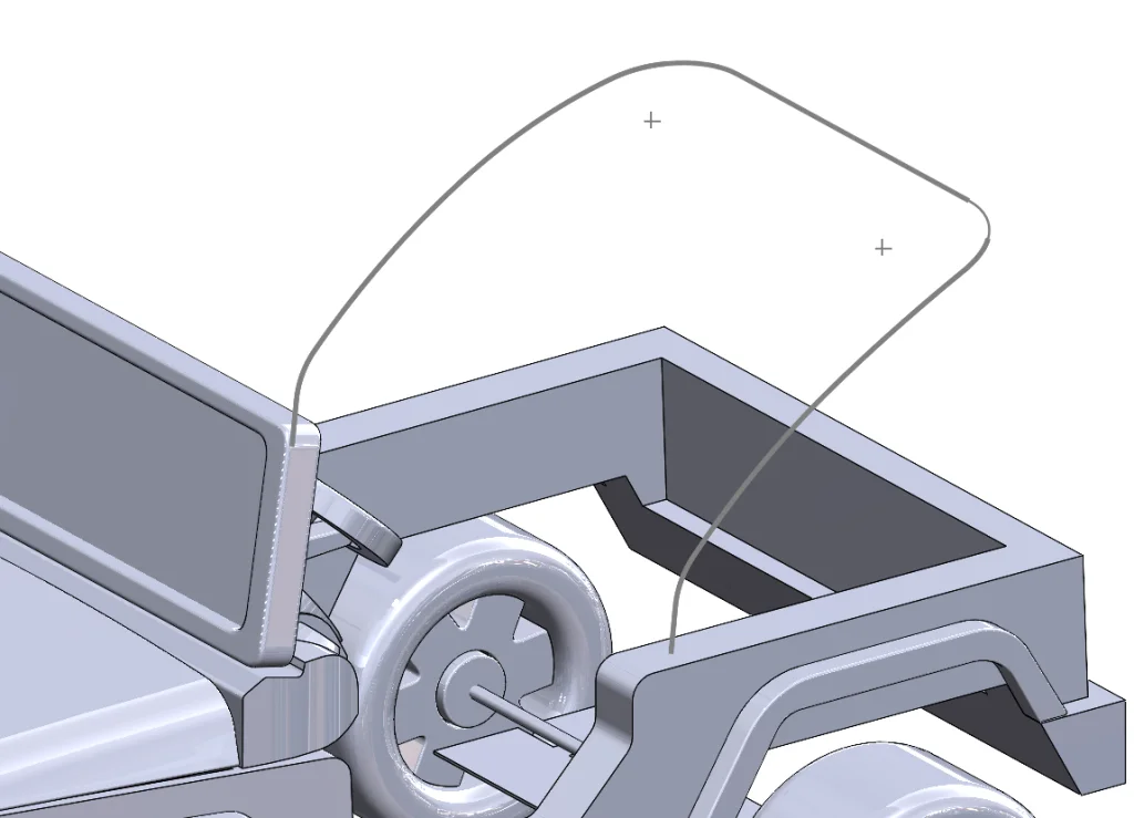
This is perfect, *except* it is obviously missing a portion. I got around this by creating a 3D Sketch, selecting the curve and using Convert Entities to bring it over, and then drawing in the portion that was missing manually, being sure to double-check my sketch against my reference pictures. I also took advantage of the fact that we can Mirror within a 3D Sketch now to complete the curve on the other side.
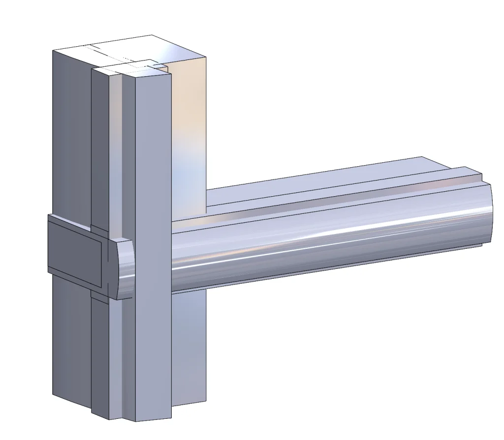
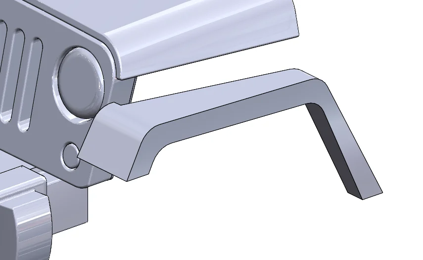
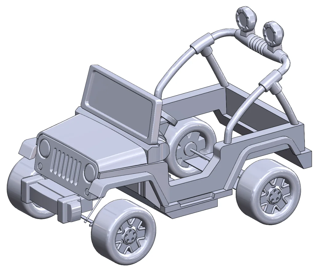
Beautiful! Now it is time to Sweep some actual material into existence. Many moons ago we would have had to first create a profile consisting of a circle at the end of our path, but today SOLIDWORKS makes it incredibly easy with the Circular Profile option inside of the Sweep command. I opted for this, obviously, setting it to a diameter of 1.25in based on the reference pictures. Then I repeated the process for the second support beam and reused the same paths (using Convert Entities in two additional 3D sketches) to create the T-joint.
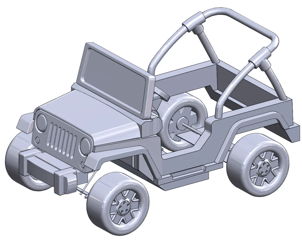
Gorgeous! Creating the Flood Lights themselves was actually pretty basic, so I won’t go into a ton of detail here except to say that I used a Revolve to create the connector and I used a Circular Pattern to create the detailed cuts around the edges of each light. I also went ahead and added fillets.
Now that we have most of the external car parts (besides seats, which were also created using the techniques previously discussed), it’s time to move on to the internals. This part was actually a bit trickier since our reference pictures don’t show everything inside the vehicle, but also critical since we are planning on adding in our electrical components and then modifying them in subsequent blogs. The trick I used here was to actually go back to the physical car and look at it… with my eyes. This required getting up, which was a good idea at this point anyway, so it was a win-win. I then approximated some of the sketches and measured some parts using digital calipers.
For the battery compartment in the front of the car, I started by hovering over the hood and hitting TAB to hide it. Then I sketched out the approximate shape that I saw after looking under the actual hood and extruded it to a depth based on the LEFT side reference picture. Next, I used the Shell command, selecting to remove the top face and extruded a top to the compartment using existing geometry and using Convert Entities.
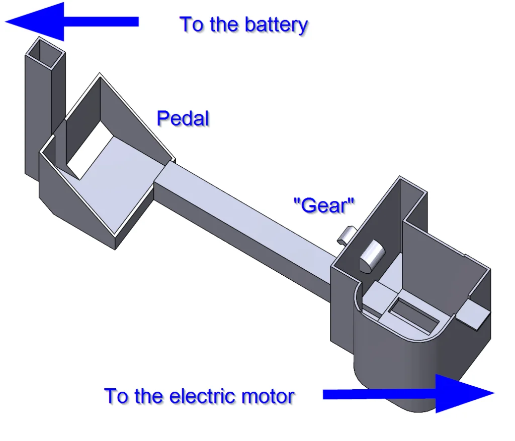
Fairly straightforward so far, right? Next, I added what I’m called the “underbelly” – again using the partial information we get from the side view – before moving on to the pedal and the area that houses the electronics from this and connects to the battery area in the front. The rest of the conduit was fairly simple after going back and forth, but I do want to mention one place that I made a mistake the first time using the Shell command. Essentially my technique was to Extrude the conduit and then Shell it out to create a path for our wires, but the timing of the Shell matters. Make sure you can visualize the end product before hollowing it out because you might want to combine multiple bodies before activating this command. Here’s what most of our conduit looks like in isolation and then in the context of our whole vehicle.
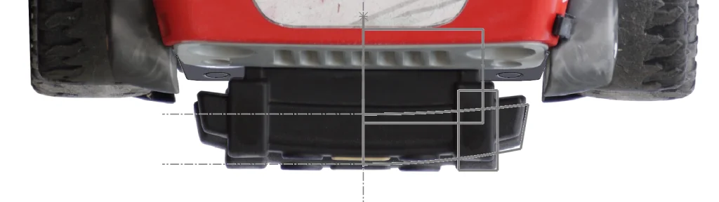
Now that our car is pretty much done, it’s time to add some details to the back and front bumpers. Jumping into a BACK view (Ctrl 2) we can trace the geometry from our reference picture.
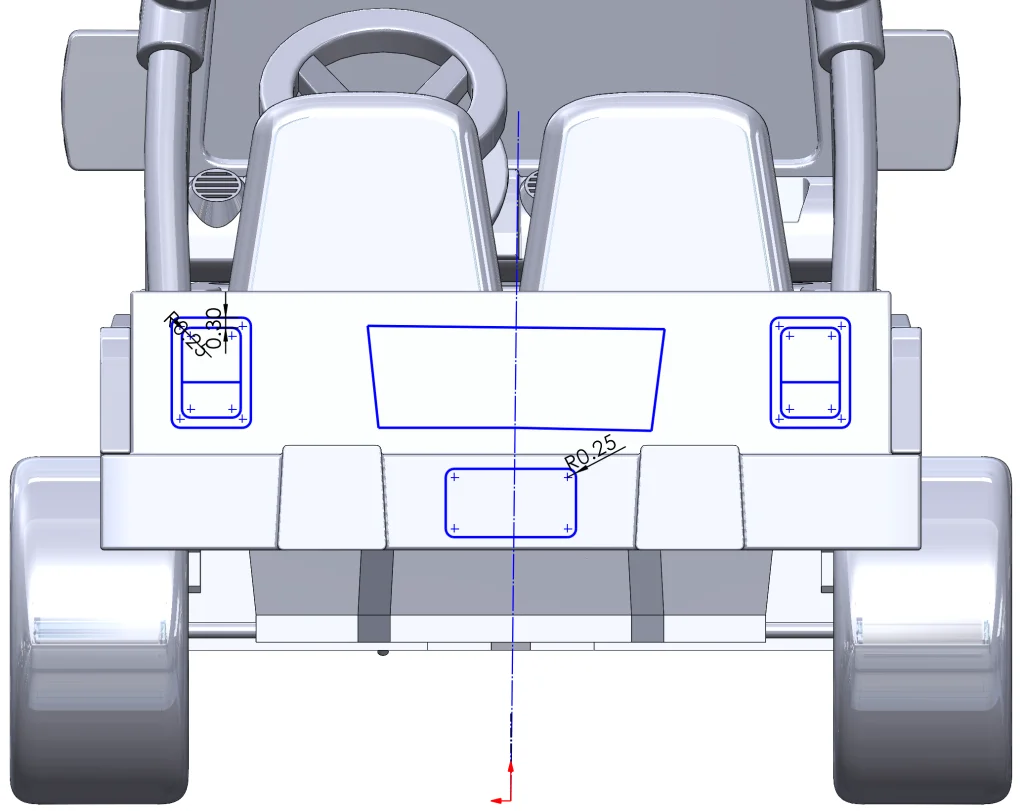
From here we can use the Split Line command, being sure to select the appropriate faces along the back bumper, to split our faces and prepare them for painting. I repeated this on the front and added some fun text at my daughter’s request.
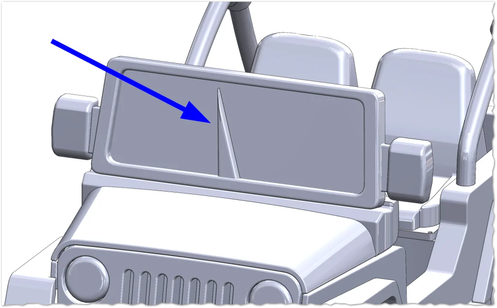
The final piece I added in was a custom unicorn horn “windshield wiper,” again at my daughter’s request, using a simple Extrude and some Fillets.
We’re done! We made it! Now it’s time to make it shiny and give it a paint job.
Step 5: Give your vehicle a dream paint job.
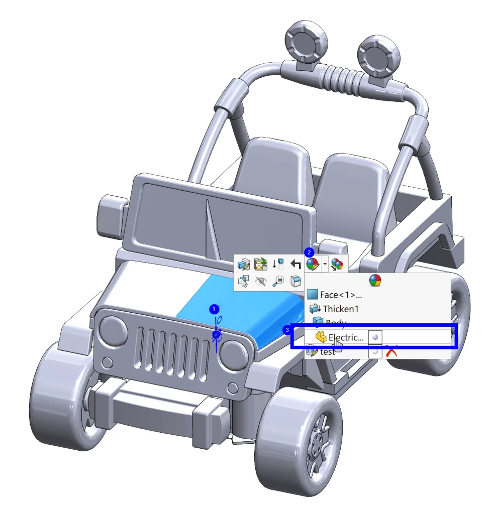
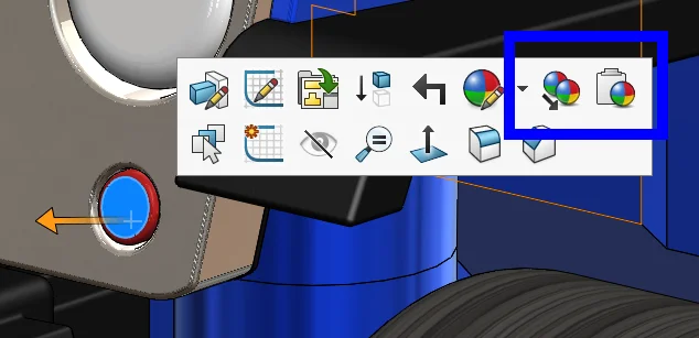
There are so many different ways to add appearances, but the way I like to do it is mostly from the graphics area. All we need to do is click on a part of the car we want to “paint” and then select the largest relevant area to paint. What I mean by this is that we want to first apply to the part, then to bodies, then features, and finally faces if we are getting really specific. I’ll give you an example.
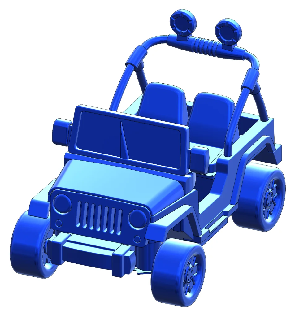
The majority of the car is going to be one color – blue, as selected by (you guessed it) my toddler. Let’s start with that by clicking anywhere and selecting the part before grabbing our blue appearance from the task pane.
This turns our entire car blue!
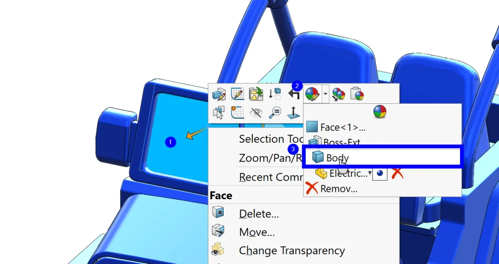
Now we can start getting a bit more specific. The seats and the window’s glass are separate bodies, so we can apply an appearance at this level. The same thing goes for most of the grill, so we can apply an appearance and get more specific with the lights and turn signals later.
Next, we can apply to specific features (the wheels and the headlights require this), and finally any faces that need to be unique. This technique ensures that we are being as efficient as possible. I also want to mention that we can copy/paste appearances between sections as needed as well using the same menu.
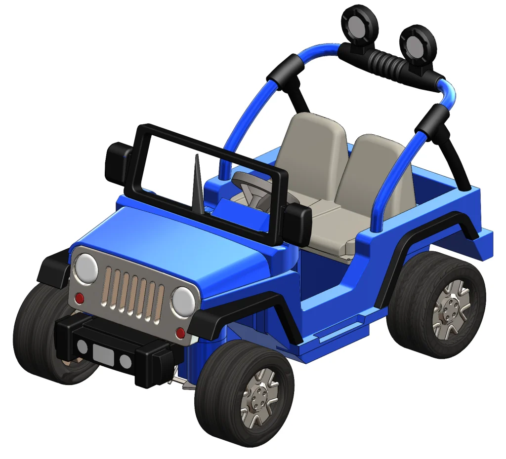
Fantastic! Our new coat of paint looks awesome.
The last thing we want to do is add some decals (NEEDS MORE UNICORNS), but let’s wait until we are in SOLIDWORKS Visualize to do this since we need to reapply there anyway. Note: I added a unique appearance to the unicorn horn in preparation for exporting so that applying a decal would be easier in Visualize.
With our SOLIDWORKS Visualize tab activated, we can go ahead and click Export Advanced to jump into Visualize. Applying decals in Visualize is easy – all we need to do is activate the Appearances tab and right-click in the background > New Decal > Image… before selecting the picture we want to use.
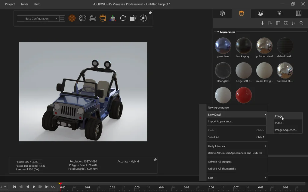
From here we can simply drag, drop, and reposition/resize as needed before rendering. I also changed the scene to brighten things up a bit and exported a video of the turntable. Here are the resulting images in all their glory:
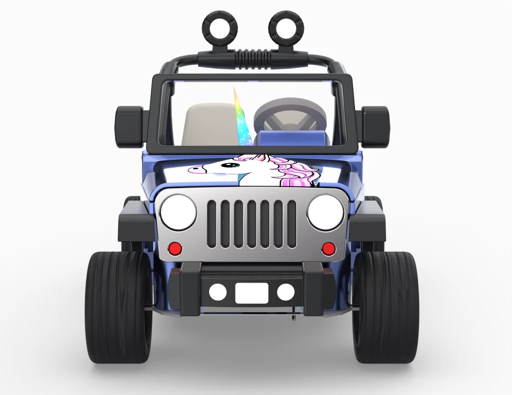
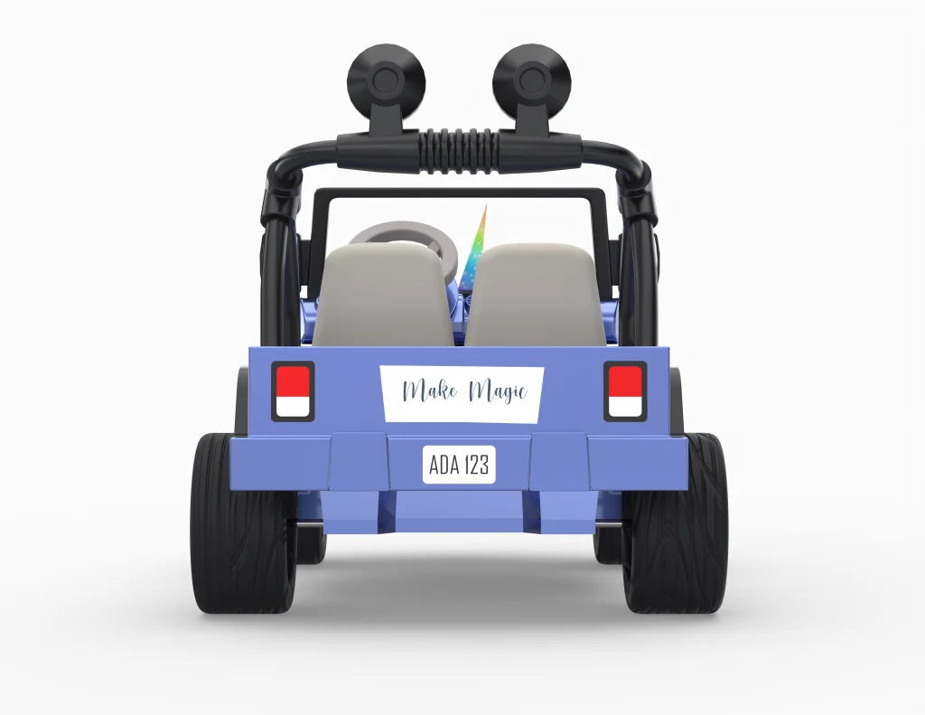
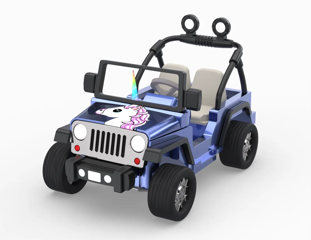

ISN’T IT MAGICAL? My daughter is so pleased. Thank you for following along on this electric vehicle journey. I hope you will join me next time as I wire everything up using SOLIDWORKS Electrical. As always, feel free to ask questions, share, and add suggestions in the comments.