
Ok, so I may have binge watched The Home Edit on Netflix recently and taken some inspiration from it. Among other things, the clear acrylic, perfectly labeled, bins that they use to organize on this show are absolutely beautiful (and practical, too, since you can see everything inside without having to pull the bin out), but there’s one problem that comes up consistently – the size of the bins doesn’t necessarily perfectly match the size of the space they need to fit into or the objects that need to fit inside. So, what’s the solution? Do we settle for a slightly smaller or larger bin than we need?
…
Never! We are engineers and we have SOLIDWORKS, so we make our own!
In this blog, we will quickly design and create some highly configurable, laser-printable, custom acrylic storage so that all of our spaces can be *perfectly* organized without any wasted space. As a bonus for any of you out there with allergies, we will also create a double tissue-box holder where one side can be used as a mini trashcan using a configuration of the same design.
Since we plan on using this design to create many different storage containers AND a tissue box, we need to make sure we design with intent. To do this, I like to start by asking the question: What will all of my designs absolutely definitely have in common? Followed quickly by: What will change? In this case, the basic shape will always be a rectangular prism, so let’s get started by sketching one of these out.
I haven’t always been a huge fan of 3D sketches, but I’ve found that the more I play with them, the more I start to really enjoy them. Plus, a rectangular prism is such a simple shape to sketch out quickly in 3D space, so let’s get started!
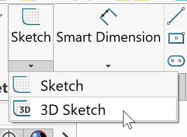
We can find the option to start a 3D sketch in the drop-down menu beneath our regular Sketch command.
Once we activate this option, we can start drawing. I like to start at a known, fixed point. In this case, this means we start at the origin. Another trick for drawing in 3D space is to make sure your view is normal to the “surface” you want to draw on. I started by drawing a quick rectangle on the Front Plane. You can see it below.
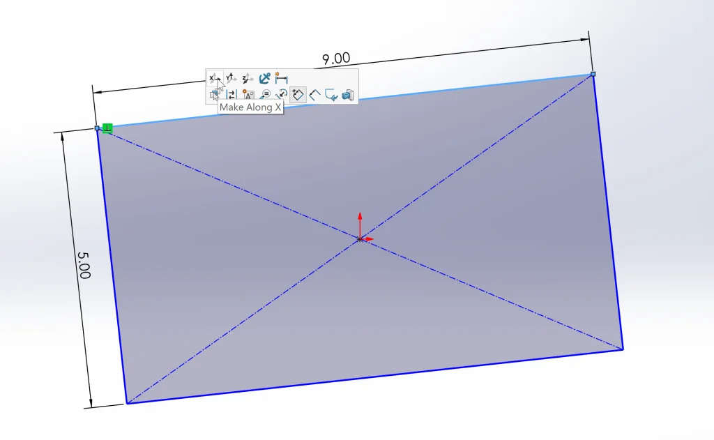
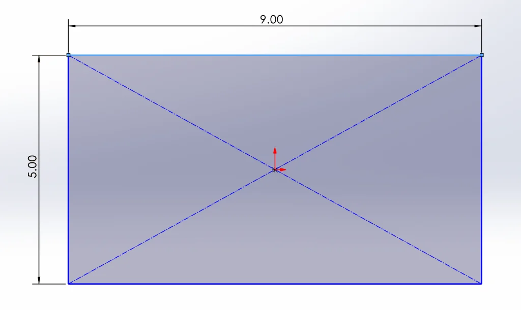
It looks great *except* we need to give it a bit of direction, if you will. If we click the upper line which is supposed to be horizontal, we get the option to Make Along X in the heads-up toolbar that pops up. After adding this relation, our rectangle is straightened out as it should be.
I repeated this process on the Right Plane and then changed everything to construction geometry before drawing out my actual rectangular prism. This next step was made simple because all of my dimensions were already there – I simply needed to draw more rectangular prisms and add relations between them and the already existing geometry. At this point, our basic shape is complete!
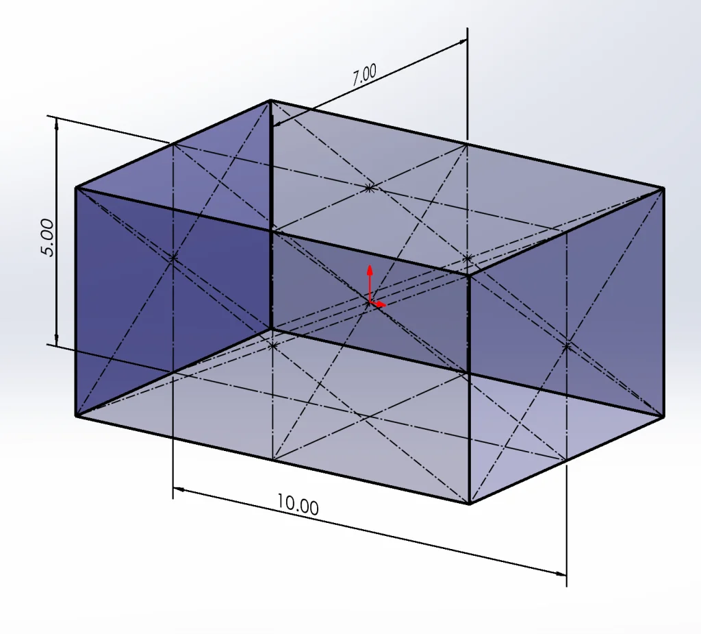
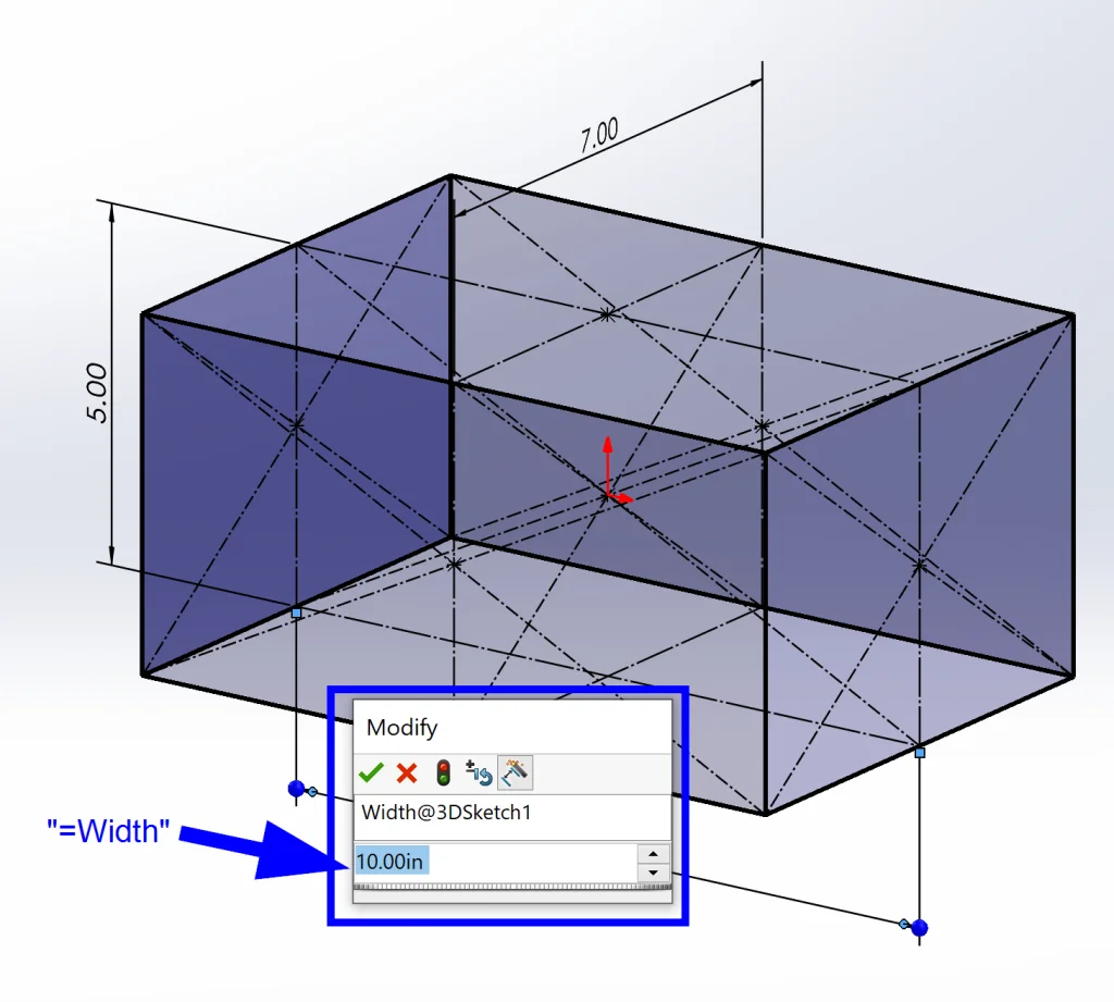
Simple, right? We’ve already started adding Intent to our design, but there’s a bit more that we can add here using Equations. For each of our dimensions, we want to go back and edit them with “=” and then either “Height” or “Width” or “Depth.” This creates global variables that can be accessed and changed later.
I also want to note that at this point I decided that these dimensions would represent the inside of my container so that I can size it to its contents. I could have easily decided to keep these dimensions as outer dimensions, but this conversion is simple enough if I want to change it later, so let’s keep moving.
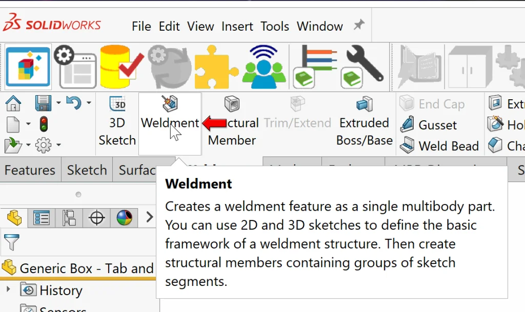
The next step is to start extruding walls around our sketch. Before doing this, I used a trick to make sure that my Extrude command wouldn’t default to Merge Result; in this design, we want to create a multibody part so that we can laser cut pieces individually. By adding a Weldment feature, the box next to Merge Result defaults to being un-checked, so let’s add that quickly.
Now we can start extruding walls, making sure that the additional sketches we make use the pre-existing Global Variables we created.
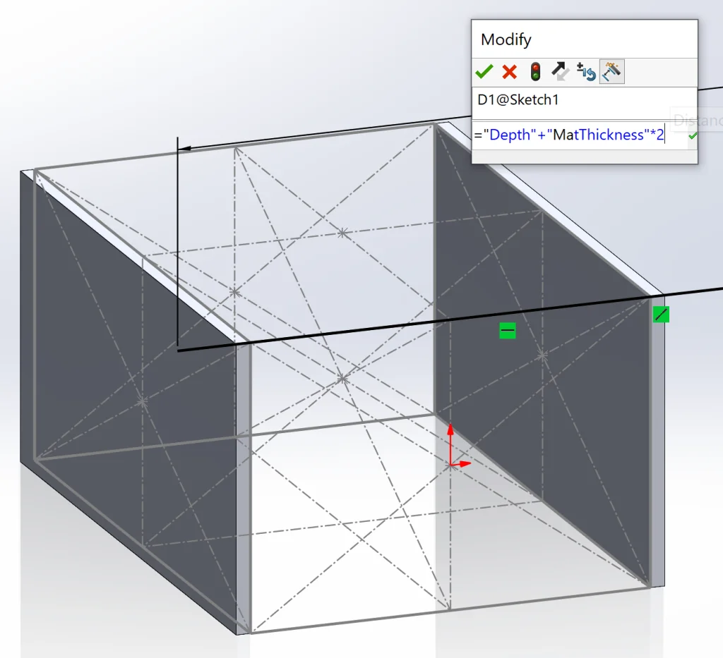
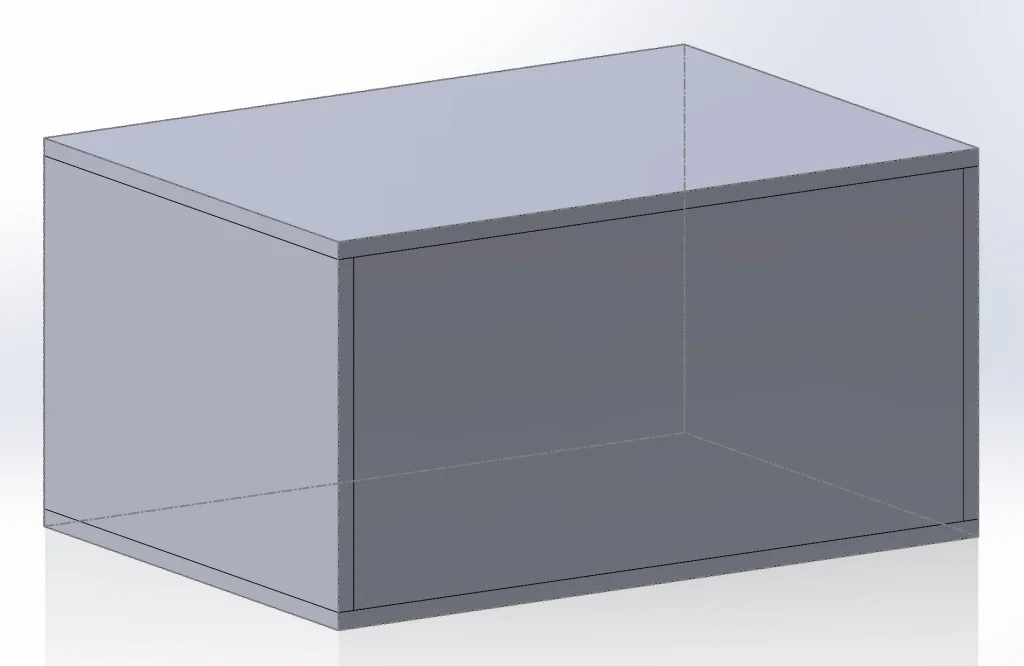
Oh! I also created a variable for thickness called MatThickness (we can’t use just “thickness” since this is already used by Sheet Metal) and set it to 0.25. Here’s what our box looks like so far:
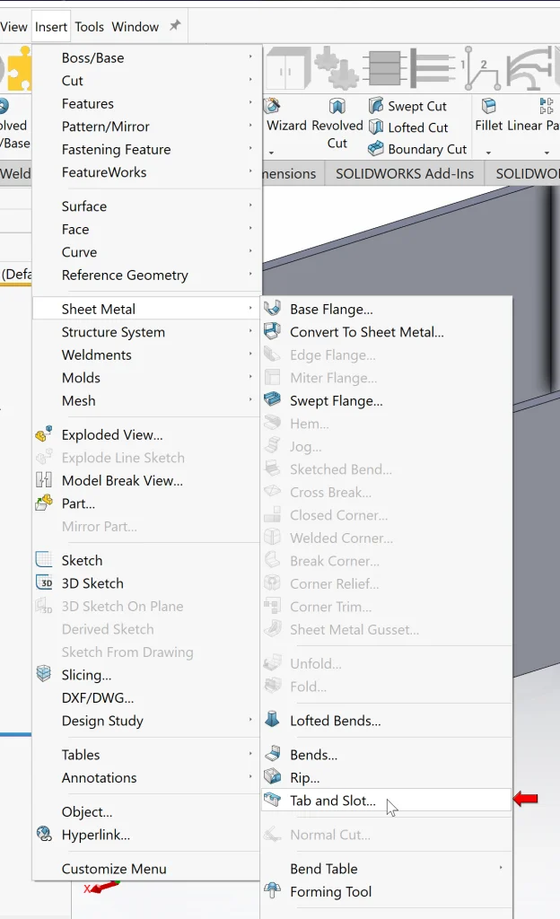
Now that we have our basic box, it is time to add some tabs and some slots that will allow us to “stick it together” after we cut it. Back in the day, I would have done this using Extrude for tabs and Cut-Extrude for slots on the corresponding body, but SOLIDWORKS developers added a tool for us that makes this incredibly simple and quick (THANK YOU). So, let’s activate the Tab and Slot command from the Sheet Metal tab in our Command Manager or from Insert > Sheet Metal > Tab and Slot.
After activating this command, we select (1) a linear tab edge, (2) a face in a direction normal to the tab face, and (3) a planar face shared by the tab edge. The first two are quite straightforward, as can be seen below, but the third face is a tiny bit tricky because we can’t see it! In order to select this face, we can right-click over the area where we know it exists and choose Select Other.
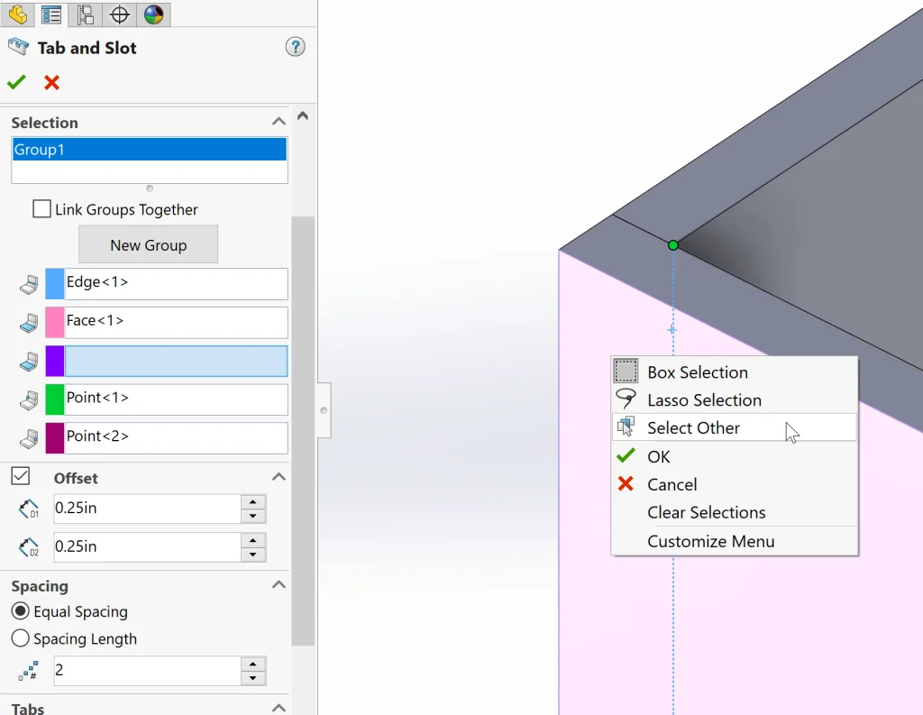
From here, we can hover over our options until the correct face is selected and highlighted in orange.
Now we can move on to additional options, including Tab Length, Thickness, etc., making sure to use our global variables in equations as much as possible since these values will be changing constantly depending on the contents of our container.
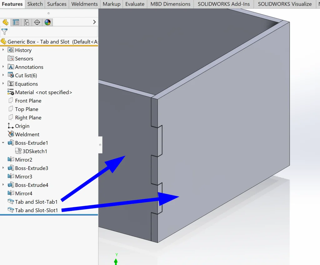
At this point, we can click the green checkmark to accept our command and take a look at the results. Looking more closely, we can see that two new features have been added to our design tree and our walls can now fit together perfectly with tabs and slots added. Fantastic!
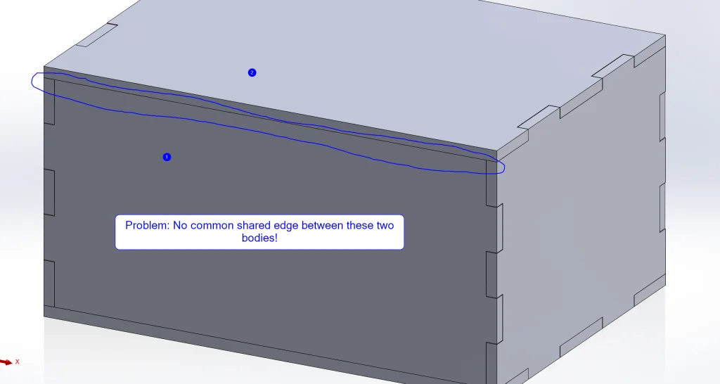
Next step: repeat! I repeated this for all edges, but then I ran into a problem! The two edges seen below can’t be joined with the Tab and Slot feature because they don’t share a common edge of the same length. Yikes!
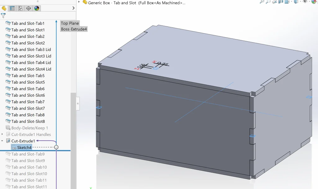
To solve this, I decided to use some trickery. First, I sketched a tiny little box on the Top Plane where I wanted to remove material and fully dimensioned it using only Global Variables (box has sides = MatThickness) and the Origin. Then I used a Cut-Extrude to temporarily remove the corners of the top and bottom pieces.
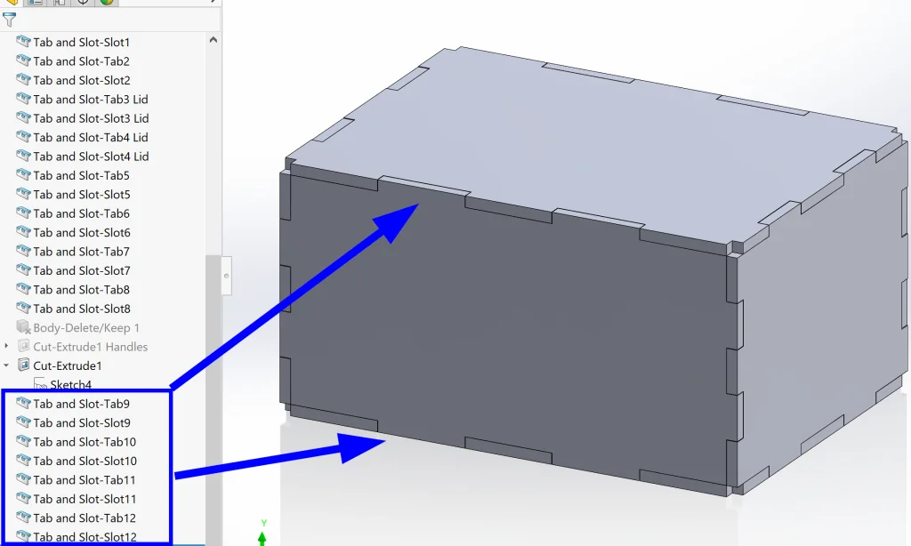
Next, I went ahead and added Tab and Slot features to the four (now matching) edges.
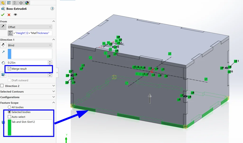
Finally, I re-used the same sketch used to remove corner material to Extrude new material in each corner. The important thing here is to make sure we check the box next to Merge Result and select the body to merge our new material with.
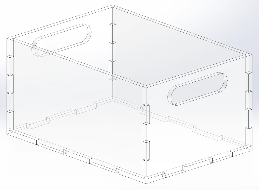
Problem solved! Now we can add some handles and edit our material.
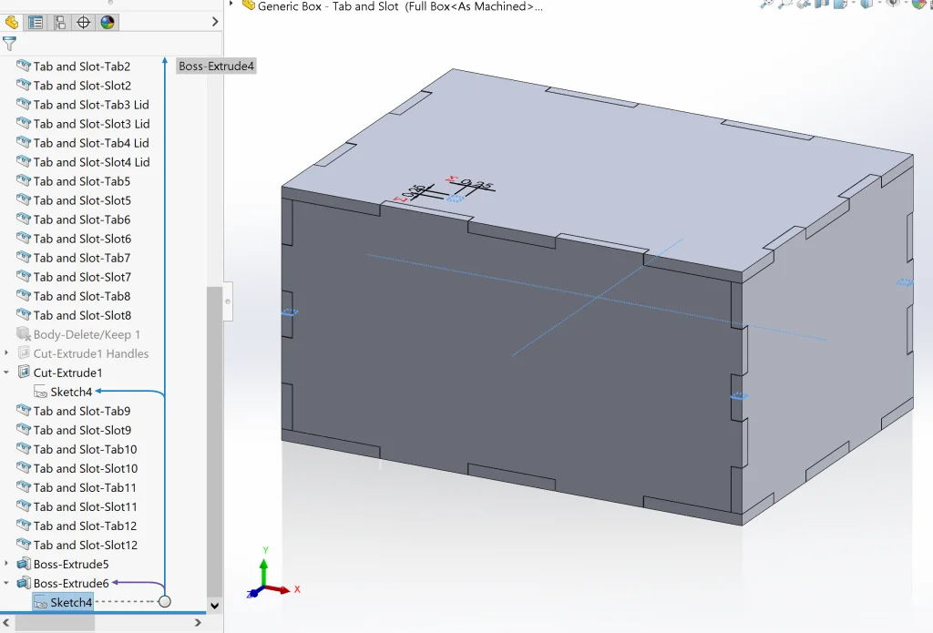
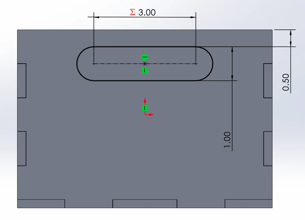
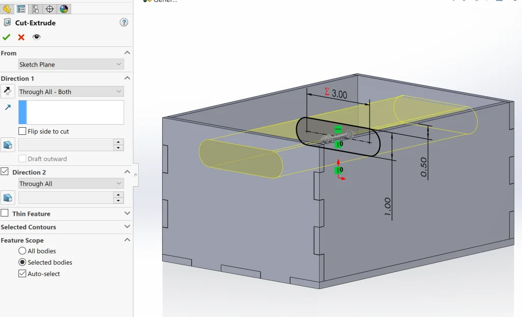
For handles, I simply sketched a Slot on the Right Plane and used Cut-Extrude with Through All- Both selected as the end condition. I should also note that I made the width of the slot dependent on the Depth of the overall box. Again, building in Design Intent!
I also created a new configuration from the Configuration Manager called “No Lid, Handles” and suppressed the upper Tab and Slot features before deleting the top “lid” body using Delete Body.
Now let’s add our material. To do this, we can simply Right-click on Material in our tree and select Edit Material. Then we can type “Acrylic” in the search bar, select our material from the list, and click on Apply.
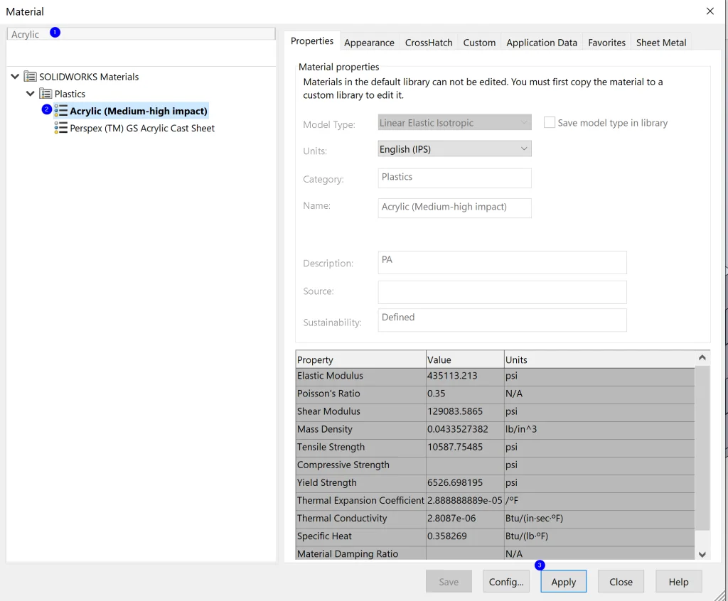
This adds all of our material properties to our part so that we can calculate mass and it also adds the appropriate appearance! Beautiful.
Now, all we need to do is make the dimensions super easy to change and we’re in business. There are so many different ways of doing this (another good option is a Design Table, for example), but today I decided I wanted to be able to use the Custom Property Tab Builder to change dimensions on the fly – just for fun and a bit of challenge.
To do this, we want to do the following:
- Add Custom Properties to the file.
- Modify our Equations so that these properties define our Global Variables.
- Create a custom Property Tab Builder file that allows us to capture (and change) these values.
First, let’s go to File > Custom Properties and add the relevant variables.
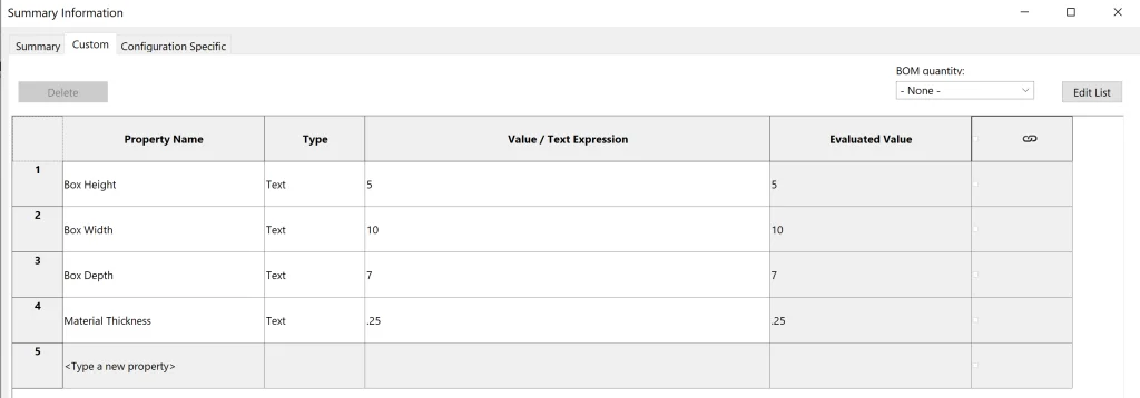
Super simple! (Note: Make sure you are on the Custom tab for this one and not Configuration Specific). Now we can right-click Equations in our FeatureManager Design Tree and select Manage. From here we want to select and clear the Value/Equation next to each variable and then click to select File Properties > [the corresponding file property from the list].
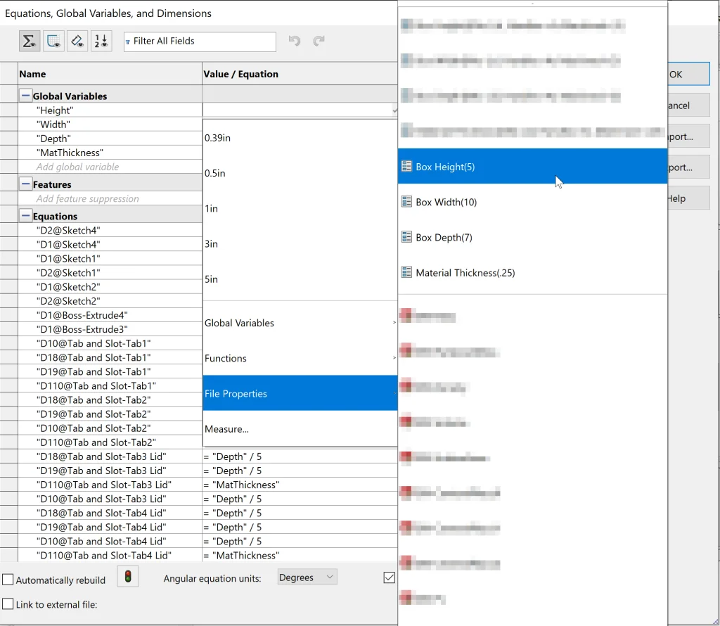
After repeating this for all of our Global Variables, we are ready to move on to the last step – building a custom Property Tab Builder configuration.
We can access the Property Tab Builder from the Custom Properties tab in our Task Manager (on the right) or from Start > All Programs > SOLIDWORKS > SOLIDWORKS Tools > Property Tab Builder 20XX.
Since we don’t have another configuration file, let’s click Create Now from the Task Manager tab (first method). This opens our (free) utility and we can start building a configuration!
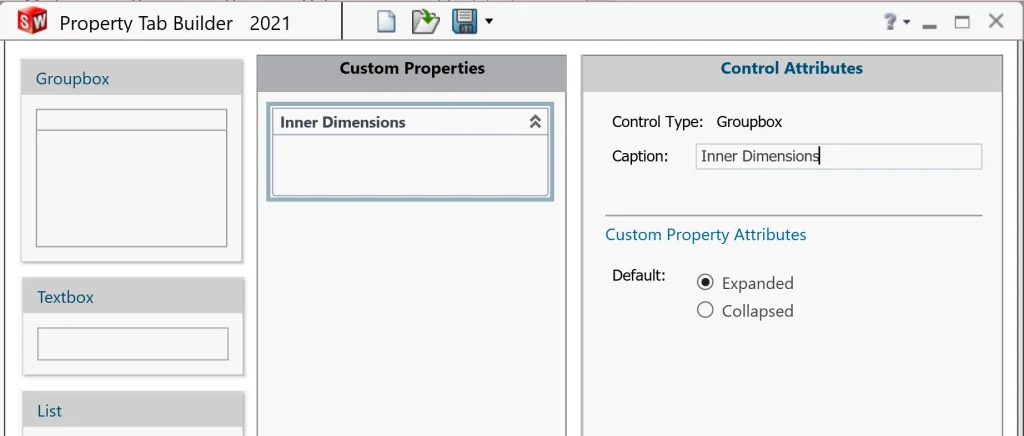
To start, we can select the default Groupbox control from the middle column and change the caption to read “Inner Dimensions.”
Then we want to drag a few of the Textbox items from the left column into the Groupbox we just re-captioned. For each of these, we want to change the Caption and the Name to match the Custom Properties we created and then enter a Value. We also want to make sure that Configurations is set to ALL.
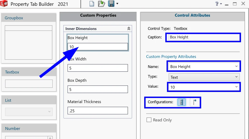
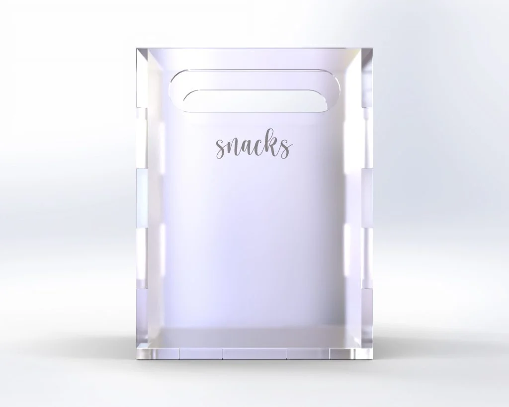
Finally, we can Save and close and go back to our part. Now, we play! Here we can see our highly configurable storage box in action:

Awesome! Now we can store ANYTHING!
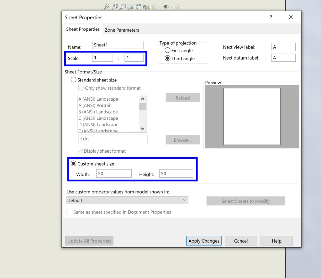
But wait, one last step! We need to create a dxf to send to our laser cutter. To do this, let’s quickly select Create Drawing from Part (under File). For Sheet Properties, we want to select to make this a Custom Size (about 20” x 40” should be more than enough space for this design) and we want to make sure the Scale is set to 1:1 before selecting Apply Changes.
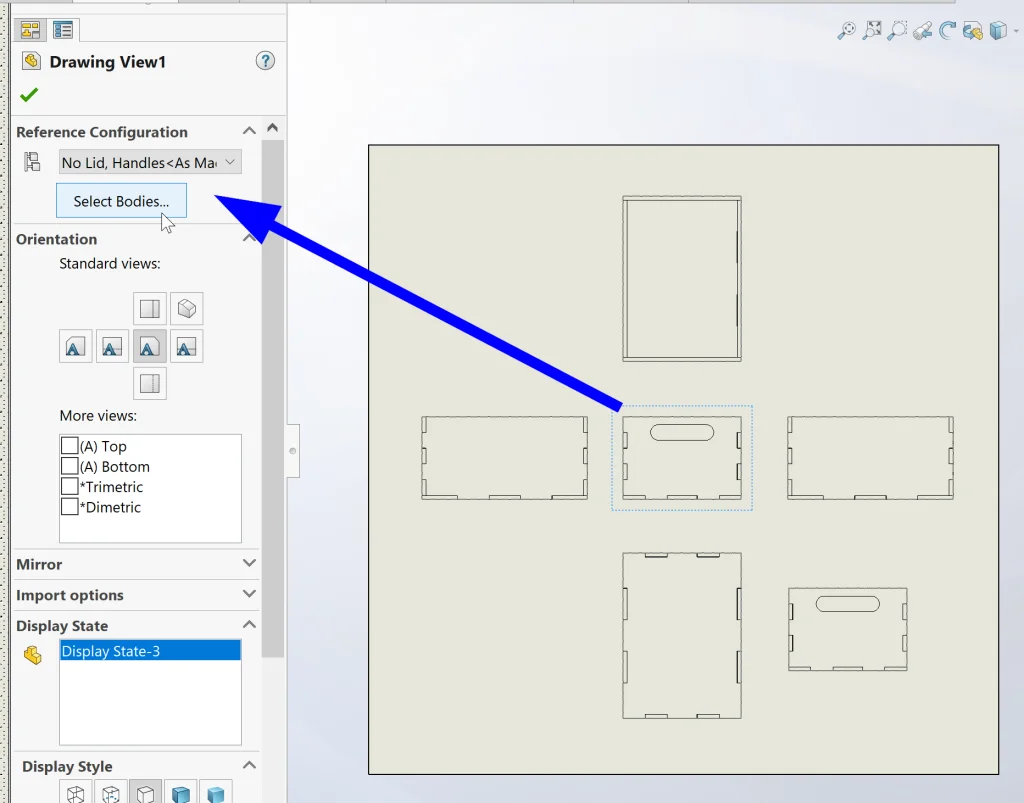
Now we can drag all of our orthogonal views onto our sheet from the View Palette, and lastly, we can select each view and choose Select Bodies… to select only the corresponding body for each view.
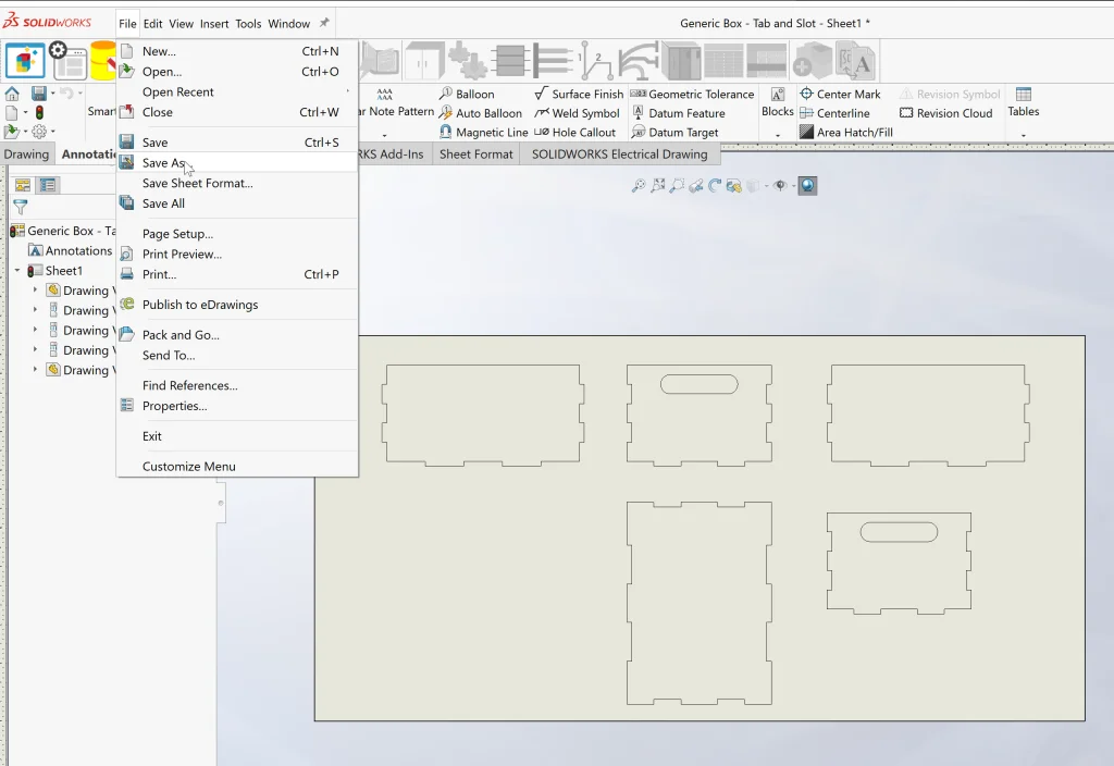
Now, all that’s left is to do a quick File > Save As… and select the type .dxf from the drop-down menu before sending this off to the printer!
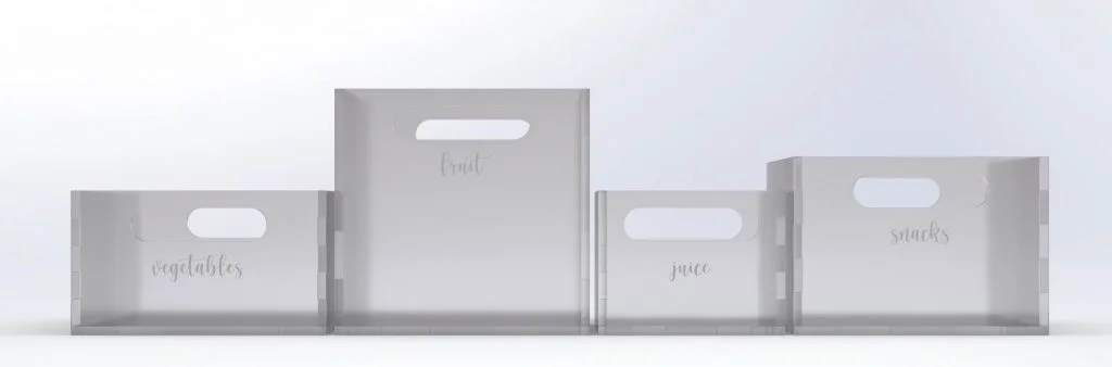
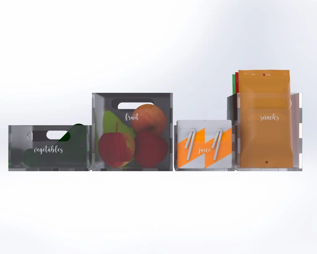
We’re done! Here’s what the final product will look like once it is assembled.
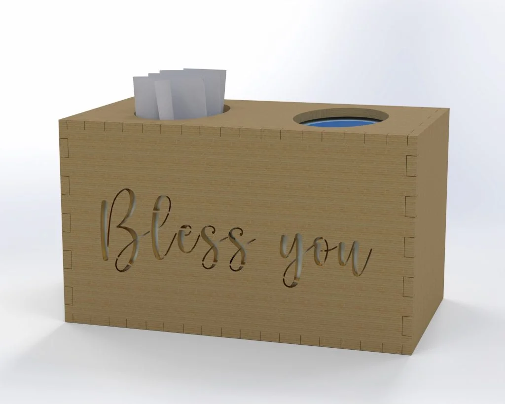
… and, to demonstrate the power of Design Intent, here’s what a slightly modified version looks like that was designed to hold tissues:
It’s perfect! Now the only thing left to do is GO CRAZY organizing my pantry, my fridge, and my closet.
Thanks for following along! If you liked this tutorial or if you have any questions or even if you would like to see something different in the next blog, please feel free to comment below and share with friends and family. See y’all at the end of spring!