

Who doesn’t love a good train? Trains are so fun whether you’re 2 or 42. In fact, my two-year-old got a wooden toy train for Christmas this year and we have ALL been having a blast playing with it since. There’s just one problem – there are NEVER enough pieces. Honestly, this has to be the fundamental issue with most building and STEM-oriented sets that exist out there, so I set out to solve the problem using… SOLIDWORKS!
In this blog we step through the process of making a virtual wooden train set using skills like making blocks, making library features, and sticking everything together with the incredibly cool magnetic mate. Let’s get started!
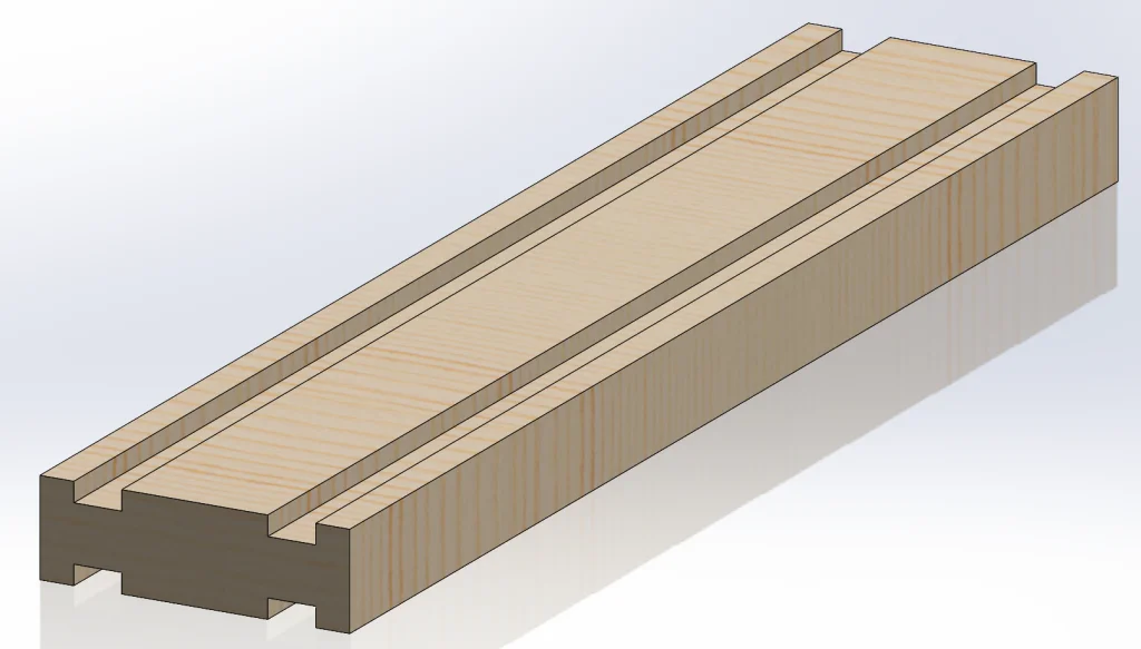
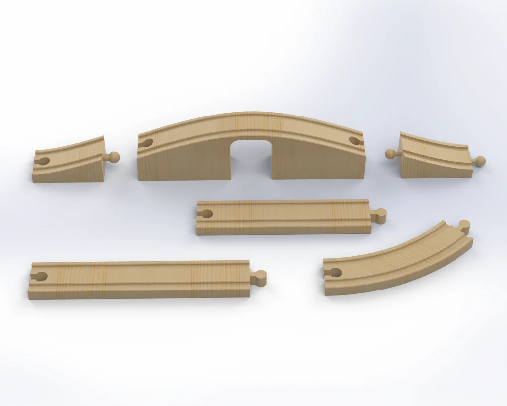
The first step in this process is going to be creating the train track pieces. For simplicity, let’s create just three of them – a long straight track, a short straight track, and a curvy piece for twists and turns.
I started by creating a simple cross-section and extruding it out. For the sake of versatility and consistency, I decided to add tracks on both sides of most pieces.
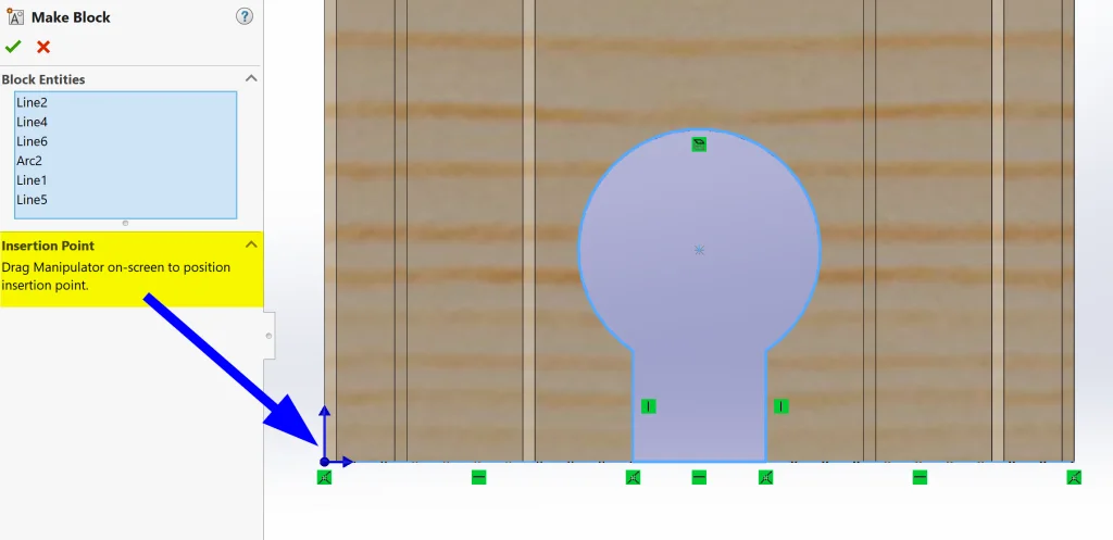
The next step is to add connectors to both ends – a male and a female. Thinking ahead and realizing that ALL of our tracks will need these pieces, I decided to make the sketches for the connectors into blocks. (Note: There are so many ways of reusing design elements in SOLIDWORKS. This one just made me happy.) To do this, all we need to do is create our sketch, select the elements we want to reuse, and select Make Block.
After we make our block, we can define the insertion point…
and then save it for future use!
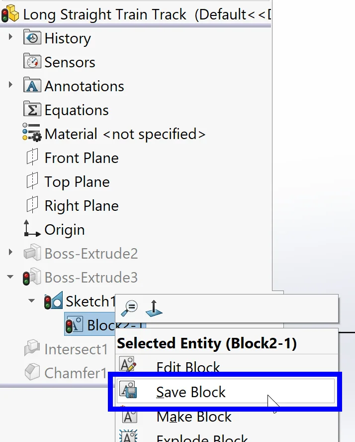
I repeated this for the male connection point as well and then cut/extruded each piece as necessary. Note: When re-using this block, we need to right-click > Explode before cut/extruding.
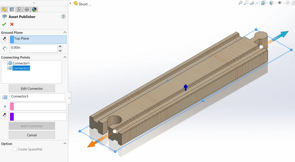
We’re almost done with our track piece already! The last part is the precursor to a bit of magic – magnetic mates! To add a magnetic mate, all we need to do is add a couple of sketch points in the middle of our connectors (it can be in a single sketch) and then go to Tools > Asset Publisher to define our connectors.
Within the Asset Publisher command, we first need to define our Ground Plane (in this case, the Top Plane will do nicely) and then select a point for connection and a face for direction. Then we click Add Connector and move on to a second connector if there is one before clicking the green checkmark to accept the command.
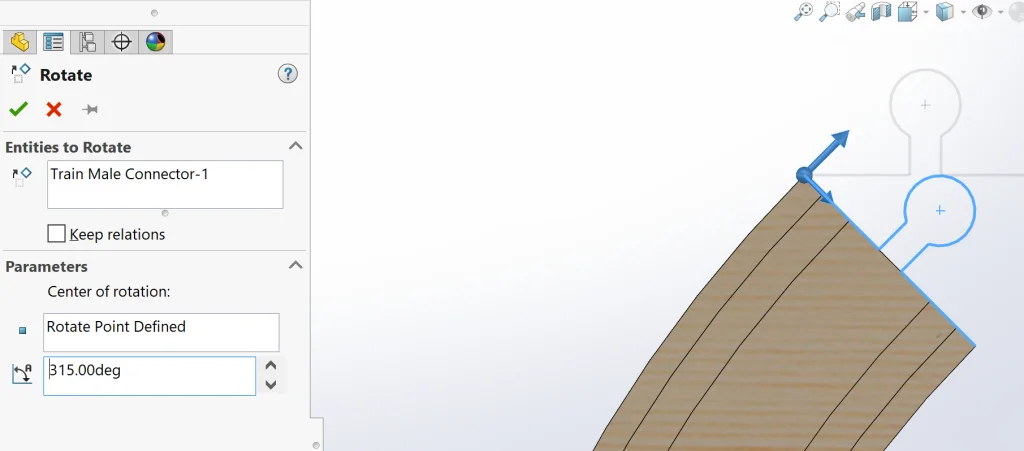
The next two pieces of track are much like the first, so I won’t go into any detail here, except to say that the curved track was created using a 45 degree revolve and therefore when we insert the male connector, we need to make sure that we rotate the sketch by 315 degrees. This can be done using the Rotate command once we are inside the sketch.
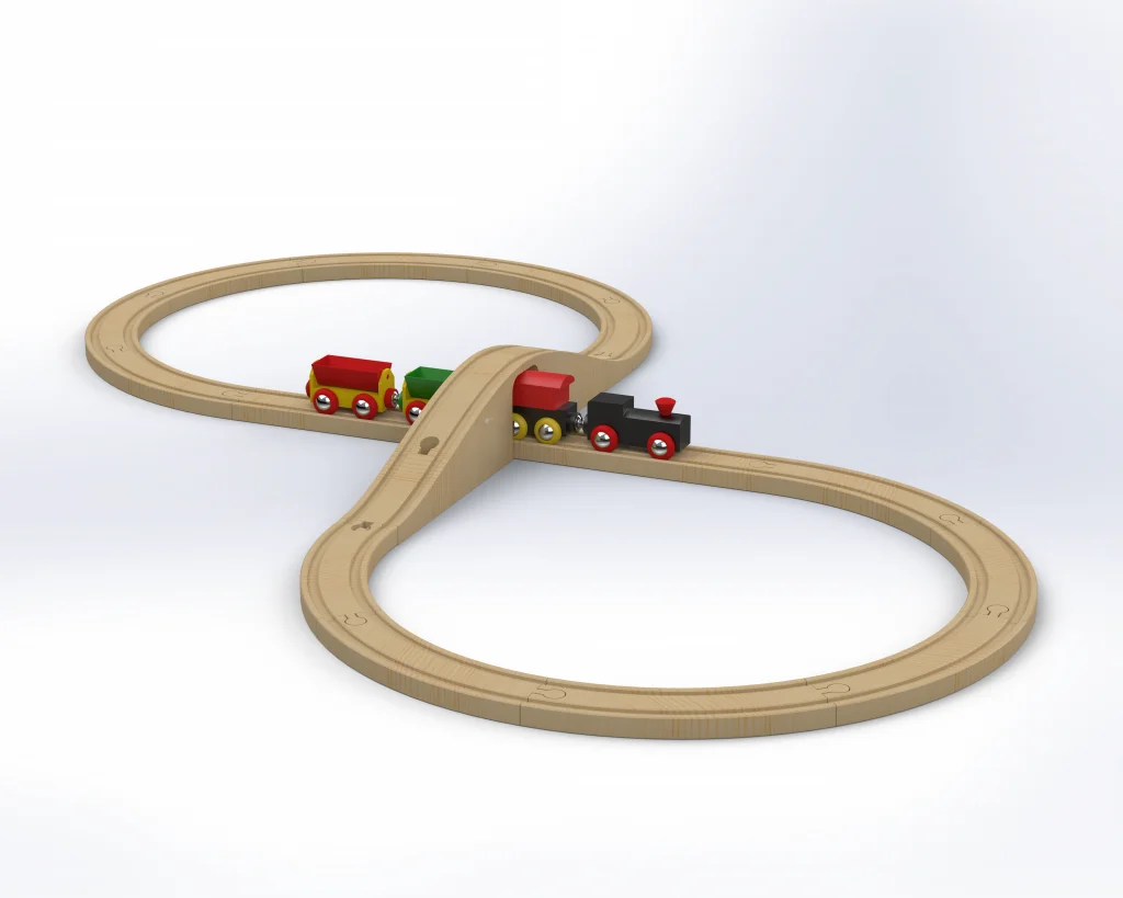
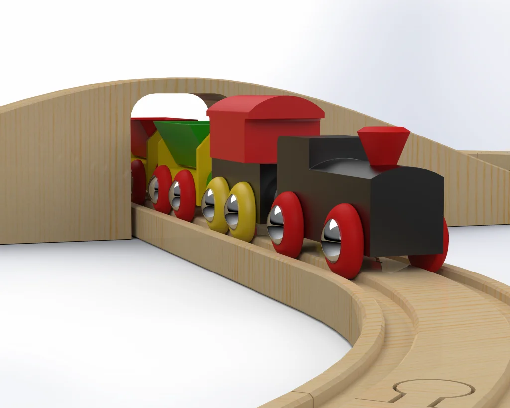
Now that we have our base train track, we can quickly create a bridge as well. This will allow us to make a figure 8 shaped track which is incredibly fun.
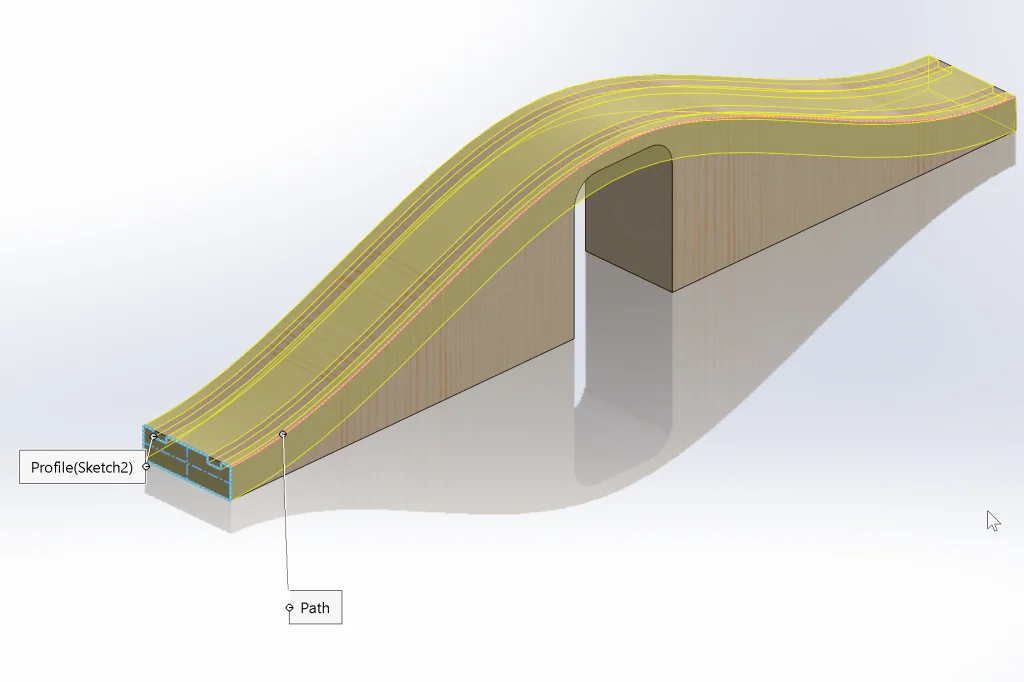
I started by taking a shortcut and doing a Save As on a straight train track to get the basic track shape into our bridge. Then I deleted most of the features and extruded the basic bridge shape. To add the tracks to the basic bridge, we can take the track shape from the original track and Sweep it along the top of the bridge, making sure to NOT merge the result immediately.
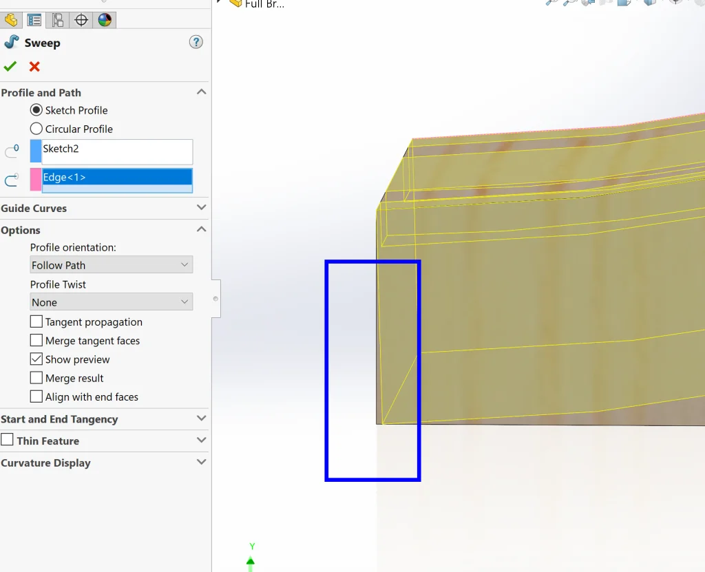
The one tricky part is that, upon initial sweep, the end isn’t quite right.
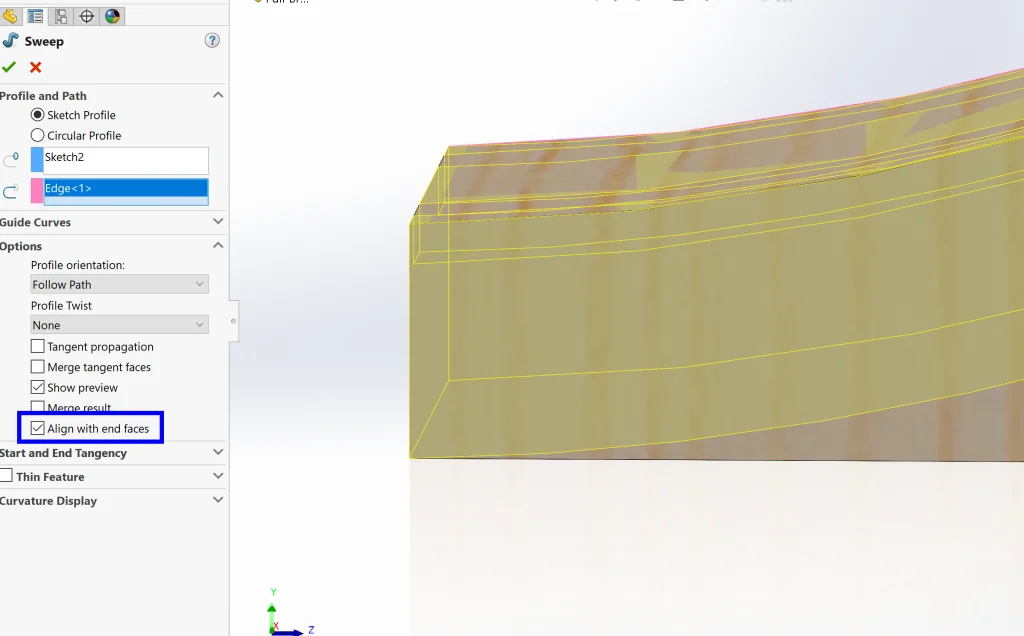
To fix this, all we need to do is check the box next to Align with end faces. See the difference? All better!
From here, the Intersect command can be used to combine the two bodies and get exactly what we need.
I also ended up breaking the bridge into 3 pieces using a simple sketch and the Split command. Once we have 3 separate bodies, we can right-click the Solid Bodies folder and use the Save Bodies… command to save out individual pieces before adding our connectors. In this case, I opted to add a revolve to the male connectors to make them more robust so that they can connect larger pieces. I finished the pieces with magnetic mates as we did before, and we’re done!
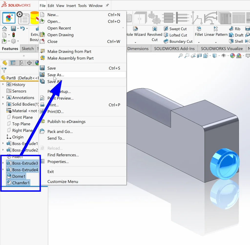
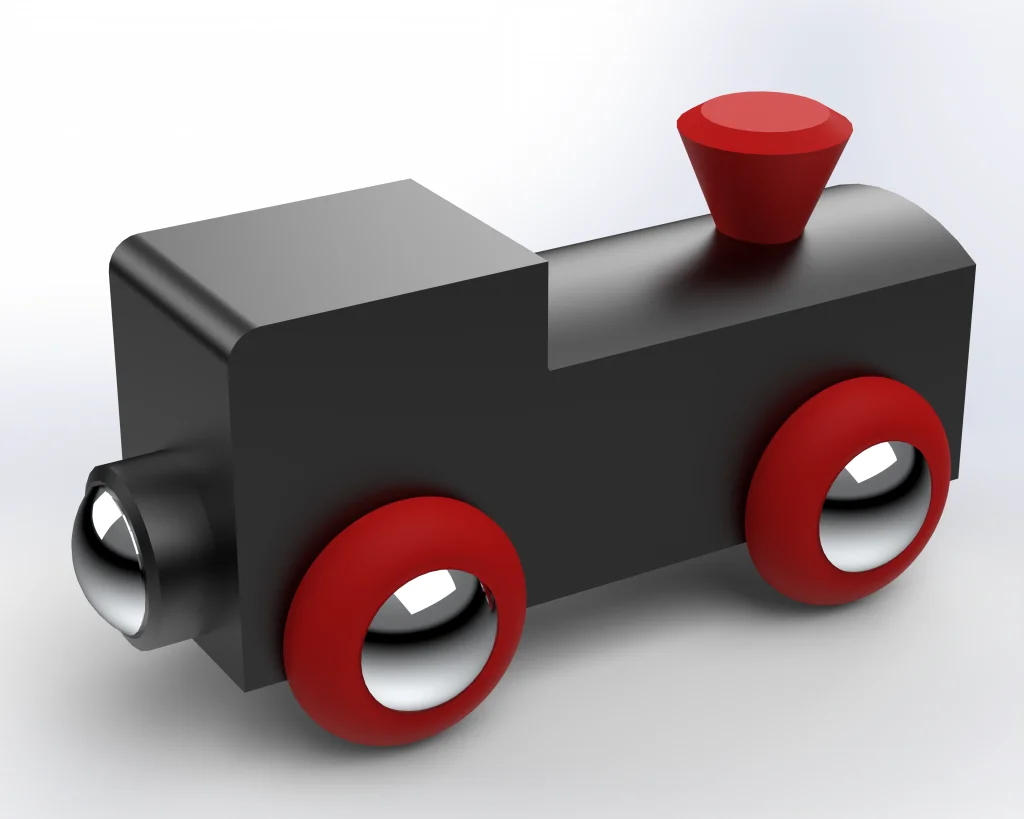
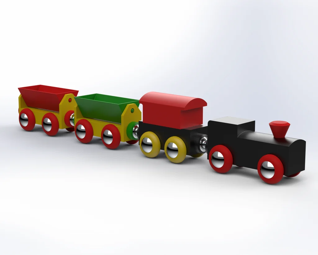
Chugging ahead, let’s create our train! Each train car consists of some very basic elements: a basic shape, four wheels, and at least one connector. I started the cab by extruding the basic shape and then used the Revolve and Dome commands to create the magnetic connector on the back side. Since each of my cars will also need magnetic connectors, I decided to make a Library Feature Part out of these elements.
To do this, all we need to do is (0) SAVE THE PART as it is, (1) select the features that we want to add to our library in our FeatureManager Design Tree and (2) go to File > Save As and choose Lib Feat Part (*.sldlfp). (Note: It helps if we build specific references into these features so that, during reuse, the features can be located.)
I repeated this process for the train’s wheels and then finished the part off with some paint and a Magnetic Mate just as we did for the train track pieces. Here’s our finished cab in all of its glory:
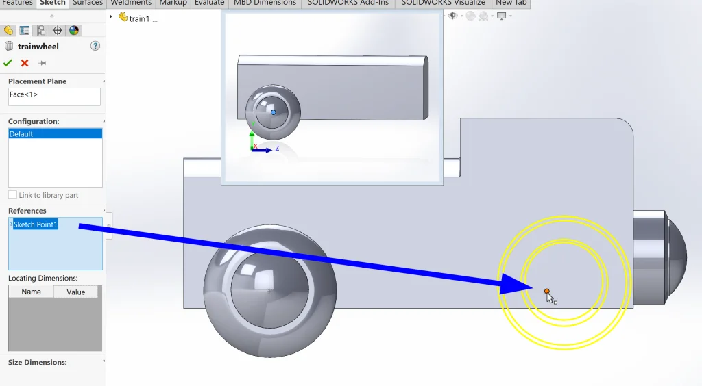
To make the rest of the train pieces, I extruded the basic shapes and then re-used our work from the first train by dragging and dropping our features from the library in the Task Pane. For the wheels, I created simple sketches to locate the library features as soon as they were dropped onto the part.
Voila! Our train is complete!
Now for the REALLY fun part – sticking everything together. Since we added magnetic mates, this is basically magic. Notice how I’m not adding any specific mates in the following video – just dragging parts until they are close enough that a line indicates that they will match.

It is just as easy to build the train on top of the track and the really cool part is that it’s SUPER simple to rearrange and add/remove cars with the magnetic mates in place. Check it out:
Here’s a quick render of the final product in SOLIDWORKS Visualize:
So fun! I hope you had fun following along and that you learned something along the way. Now please excuse me while I go make the most EPIC train that has ever been known. I think making one that circles my house is a good start, yeah?