How to Tolerance a Part: Simple Steps to Specify Part Tolerances – Part II
This is a sequel to ‘How to Tolerance a Part: Simple Steps to Specify Part Tolerances – Part I‘ provided last month.
Design for Assembly – Criteria for Tolerance Selection contd..
Choice of Assembly process determines the selection of Datums and their precedence in Tolerance specification.
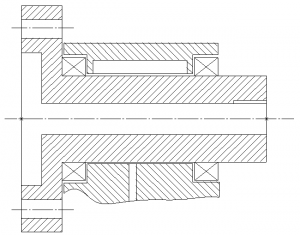
Take the case of Coupler-Shaft Assembly shown as under.

If the bearings and housing are mounted onto the coupler-shaft then it drives the location and orientation of the downstream components. If the coupler-shaft is inserted into the housing that has bearings located, then it gets located and oriented with respect to the upstream assembly of housing and bearings. In the former case, the coupler-shaft would be located and oriented with respect to the spigot-recess on the left face and fastened on the PCD flange. Then, the spigot recess, defined as Datum Feature of Size, would control the location of all features including the shaft Outer Diameter.
However, if the shaft were to assemble itself onto the bearing and housing assembly, then the shaft Outer Diameter would be the Datum Feature of Size, controlling the tolerances of all features and features of sizes, in terms of location and orientation.
Needless to say, DFM plays a critical part in determining features and/or features of sizes that would need to be used as datums. Datum and Datum sequence (in the Datum Reference Frame) are critical to the success of a product in terms of fit and function.
Functional Datum Selection
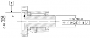
Continuing with the same example, if the couple-shaft is located and oriented with respect to the spigot recess on the left and its associated face, on another upstream component/ assembly, then the datum selection shown as under along with the datum precedence would be relevant.

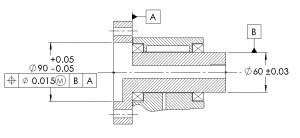
If the coupler-shaft is assembled onto the housing with bearings, then functional datums would be as shown in the figure below.

Tolerance Specification for Features
Selection of Tolerances are based on Fit and Functional requirements. In the example shown above, for the coupler-shaft, the shaft outer diameter would have a Bearing Fit tolerance. The spigot diameter would again have tolerances based on fit with the upstream component. The faces, used as Datum A, would then be ‘oriented’ with respect to the axis taken as Datum B. If the first assembly sequence is chosen, Datum B would refer to the spigot axis. If the alternate assembly method is used, Datum B would refer to the shaft Axis. Datums are derived out of physical features and hence specified as attached to outlines of features/ features of sizes. Orientation control on Datum B with the axis taken as the reference Datum, would implicitly control form (for example, Flatness) since it is a Level III control and Form is Level II control. Sometimes it is a good practice to explicitly specify tolerances of form on flat surfaces to prevent ‘rocking’ datums and havoc arising out of the size tolerance specifications.
In the example, since the coupler-shaft would rotate about the assembly axis defined by upstream component/ assembly, the centre of mass of the rotating element, away from the ‘instantaneous axis’ of the assembly influences vibration levels at the bearings. To keep the eccentricity minimal, it is important that the centre of mass deviation from axis of rotation is kept to a minimum. This would mean that the ‘tolerance’ should not ‘grow’ as one moves away from Maximum Material Condition (MMC) towards Least Material Condition (LMC). In other words, tolerance of position as shown in both figures, above, should preferably be Regardless of Feature Size (RFS) and not MMC as shown in the Feature Control frames. The value of the position tolerance would depend on the permissible eccentricity and process capability. Needless to say, cost of poor quality due to Bearing failure and replacement should weight on the mind of the designer when arriving at stated tolerances.
More to come in the next part of this series….


