
One of the big advantages of the SOLIDWORKS Simulation products is the possibility to test assemblies. This gives you a better understanding of the behaviour of parts during different loading types in an assembly. An important part of the study setup is the contact definition, so SOLIDWORKS Simulation knows how the different parts must be connected to each other. In this Tech Blog I want to give you a brief overview of the different contact options: Global Contact, Component Contact and Contact Set.
Short background With contacts it’s possible to define the way parts are connected to each other. The following three options are available:
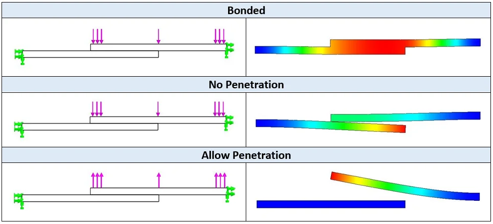
- Bonded With this option two parts behave as if they were welded. So, in fact two parts will act as one part.
- No Penetration This contact type prevents interference between two parts, but allows gaps to form. Note that this is the most time-consuming option to solve.
- Allow Penetration This option treats two parts as disjointed. The loads are allowed to cause interference between parts. Using this option can save solution time if the applied loads do not cause interference, so you do not need to apply a No Penetration contact type between parts. Do NOT use this option unless you are 100% sure that loads will not cause interference.

The contact options mentioned above can be defined at different levels in a Simulation study, these are: Global Contact, Component Contact and Contact Set. Let’s take a look how to use these in a proper way.
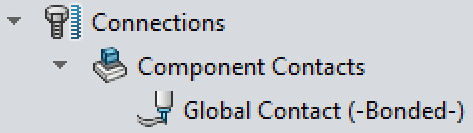
Global Contact When analysing an assembly or multibody part, the Global Contact condition will be defined automatically in your study. And its type will be set to Bonded by default. You can see this in the Connections folder in the Study Tree.
It’s important to know that Global Contact is only going to act at initially touching faces between all components in the assembly. So, if there is an initial gap (no matter how small it is) between the faces of two parts, then the Global Contact definition is not going to do anything. In this case the user has to define a Contact Set, which will be discussed later in this blog.
In some cases, you will need to define a Global Contact condition manually. To do this, right-click the Connections folder in the Study Tree and select Component Contact. Then, in the Component Contact PropertyManager, under Components, select Global Contact. This will automatically select the complete multibody part or top-level assembly. After you selected the desired Contact Type, you can hit OK and the Global Contact is defined.
Component Contact The Component Contact condition behaves the same as Global Contact. This means that, in the case of Component Contact, the faces of two parts need to be initially touching. A Component Contact condition will always overrule the Global Contact condition. So, when all parts are bonded together by a Global Contact, you can still apply a No Penetration contact between some parts in the assembly.
To apply a Component Contact, right-click the Connections folder in the Study Tree and select Component Contact. Then, in the Component Contact PropertyManager, under Components, select the bodies to which you want to apply the chosen Contact option. Note that the chosen Contact option will be applied between all the touching faces of all selected components. If you want to apply an exception to one of the faces selected by the Component Contact, you will need to apply a Contact Set, which will be discussed later in this blog.
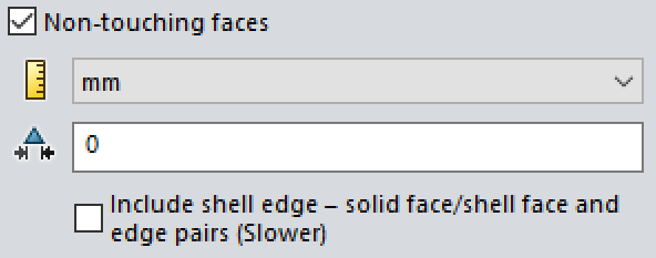
Starting from SOLIDWORKS 2016 a new option was added to the Component Contact PropertyManager: Non-touching faces. It is only available when the Contact Type is set to Bonded. The option works with both Global and Component Contact and it breaks with the traditional method that faces for a Global or Component Contact need to be initially touching. So, with this option checked, the program creates bonded contact between face pairs that are not touching, but are within a user-specified maximum distance. This can be a real time-saver!
Contact Set During the explanation of the Global Contact and Component Contact conditions, I already hinted a bit about the use of the Contact Set condition. So here are the main two reasons why you should choose for a Contact Set:
- Exceptions A Contact Set condition overrules the definition of a Global and/or Component Contact condition. So, this is the ultimate tool to get the right contact definition at the location you desire.
- Initial gaps As mentioned earlier the Global and Component Contact conditions can only be used for initially touching faces. So, with the help of a Contac Set you can close this gap and define the right contact definition for these areas.
To apply a Contact Set, right-click the Connections folder in the Study Tree and select Contact Set. Then, in the Contact Sets PropertyManager, under Type, select the faces to which you want to apply the chosen Contact option.
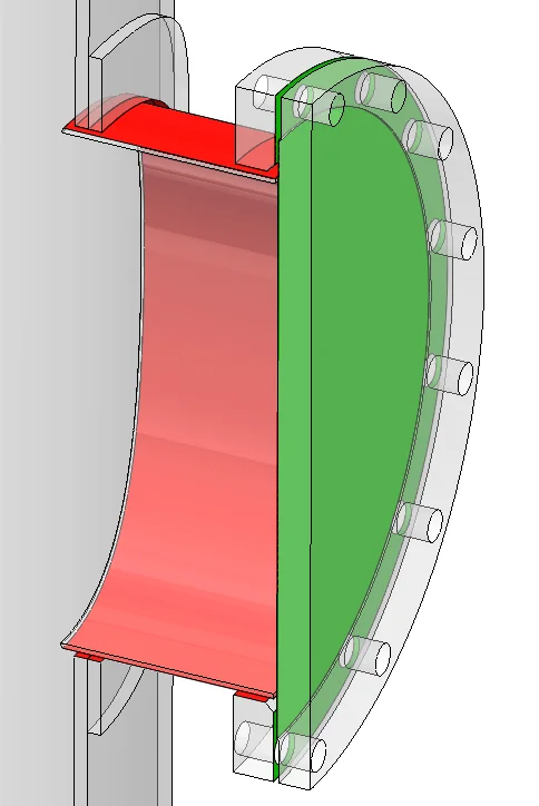
It is a good habit to select the largest face in the bottom selection box (Faces for Set 2), because this face may be meshed with a larger element size. This is especially interesting for No Penetration contacts. Make sure to define contact sets per one face reference. For example, in the image below, one contact set is defined for the red faces and one contact set is defined for the green faces. Would all of these faces be selected in one contact set condition, then the program is not able to make the right contact conditions.
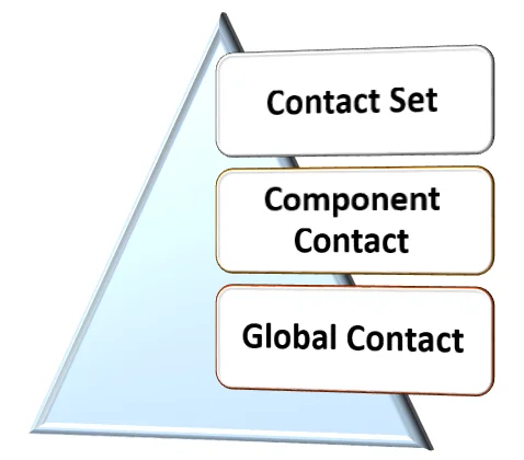
Conclusion As we have seen it is quite important to use the right contact definition at the right location in your Simulation Study. To summarize: Specify Global, Component, and Contact Set definitions efficiently to define the problem. Note that for Global and Component Contact, you do not select specific entities since they apply only to initially touching areas. Use Global Contact to define the most common desired condition and then override it by specifying Component Contacts and Contact Sets wherever needed. So, Global Contact is overruled by Component Contact, and Contact Set will overrule them both. The image below covers the hierarchy of contact definitions and is good to remember.
This is bringing me to the end of this tech blog for now. I hope you enjoyed reading it and learned some valuable things to use in your next Simulation Study!
Written by Martijn Visser