
In this post about the W16 engine I will detail the build of the main internal parts of the Cylinder Head: the rocker fingers, the valves and the camshaft.
See detailed explanations in the extended entry at the end of the post.
Download the camshaft assembly, the valves and the rocker finger assembly.
Thank you for reading about this build and stay tuned for the next post which will detail the calculation of the camshaft phase angles and the mating of the components that go inside the cylinder heads.
George Bucsan
Worcester Polytechnic Institute
Aerospace Engineering, 2014
The first part I will write about is the valve, and its two versions: the long and the short valve. They are made using a revolved boss. For the short valve, the length (2.778’’) comes from approximations on the reference drawing and a small adjustment: the head of the valve (the part that is touched by the rocker fingers) is a hemisphere. It is made like that to enable mating in Solidworks 2010. For more about this detail read the next blog post. The bottom part of the valve has an approximated diameter of .45’’ and a “guestimated” spline to connect back to the main shaft of thickness .31’’. The only difference between the short and long valve is the length: 3.715’’ for the long one.
The next part is the finger (later, the two-finger assembly). The finger is built from approximating two dimensions: the length and the width: 1.572’’ and .7’’ . It is not accurately constructed to model the real rocker, but it is made so that it looks alike and it fulfills its role in the movement of the engine parts. The basic extrude sketch:
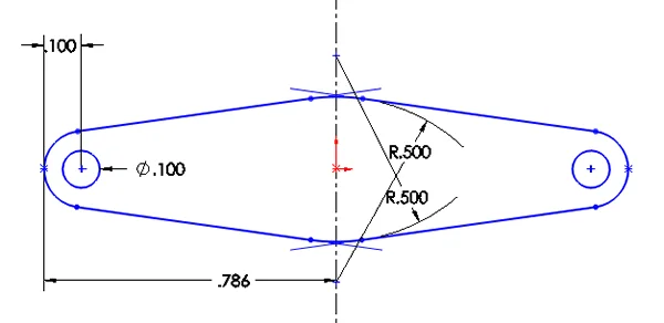
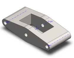
The ends are rounded in order to facilitate later mating. The holes are made to accommodate the pin that connects two fingers to the cylinder head. The next two elements added are a top plane – rectangular extrude to accommodate the roller to sit inside the finger and a right-plane circular hole to allow the roller to be attached. Through each attachment hole there is an axis to facilitate later mating.
The roller is composed of two mid-plane extrudes of two circles .1’’ and .71’’ in diameter.
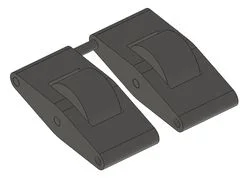
Each “fingers” assembly has two fingers, each one with a roller inside, and joined through a pin.
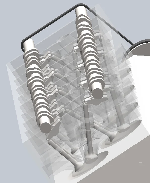
The most complex assembly in this post is the camshaft. The camshaft is comprised of 16 attached to a central shaft. Each cam is a simple extrude of the following sketch:
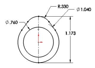
This was obtained through approximations and experimenting with the movement of the engine parts once in they were in place. The most important aspect is the tangency between all touching curves.
The cams are grouped in pairs of two at different phase angles. Because there are four parallel cam shafts and each cam shaft serves two different rows of cylinders – intake on one and exhaust on the other – the calculation of the phase angles posed a real problem. This problem will be solved in detail in the next post.