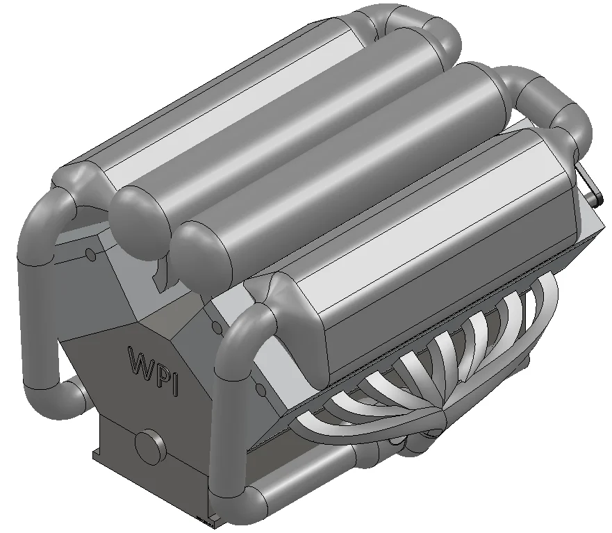

This is a model of the W16 Turbo engine used in the world’s fastest production car. I modeled it as a final project for the Introduction to CAD class. During the next few weeks I will walk you through the build, post the files and explain some of the math behind it. This post will cover the modeling of the basic piston:
Here is the link to the document that I used as a reference.
“The W Engine Concept – Self Study Program” VW of America, 2002, available here
See detailed explanation in the extended entry at the end of the post.
Thank you for reading about this build and stay tuned for the next post which will include the Conrod and the Piston-Rod-Rings Assembly.
George Bucsan
Worcester Polytechnic Institute
Aerospace Engineering, 2014
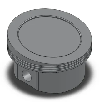
The basic shape of the piston is a cylinder, therefore I chose to start with creating a sketch on the front plane and a circle. I then extruded the circle.
The characteristic feature of W and VR engines made by VW-Audi is the top surface which is cut at a 15/2=7.5° angle. This will be modeled simply through an extruded cut (through all) in a plane in which the piston appears to be rectangular – I chose the front plane.
The next feature consists of the ring grooves. Because they are circular, I used a revolved cut and a front-plane sketch which defines the profile of the rings (rectangular).
For this type of engine, the piston does not have a uniform thickness along its axis; it is thinned in the bottom part, starting from just under the rings. For this, I used a revolved cut similar to the one above but on a bigger scale.
On the thinned side of the piston, there are two parallel plane surfaces, perpendicular to the pin’s axis. As the surfaces are parallel to the right plane, they appear as lines in the front plane. For this reason, I used two symmetric rectangles on the sketch. I then extruded the sketch with a “through all” option.
The top part of the piston has a small cavity to facilitate the burning of the fuel. Given the plane it is made on and the ellipsis shape, I chose to sketch directly on the top face of the piston, convert the surface outline into another entity and then create a similar, smaller one, with Offset Entities. Through a simple “blind” extruded cut I reached the desired shape.
Because the piston is still not carved inside, I decided to scoop out some material (extruded cut ) starting from a sketch on the bottom surface. The thick parts correspond to the place where the pin attaches and are parallel with the surfaces created before. Through a circular sketch on one of those surfaces and another extruded cut I created the holes for the pin.
For not touching the counterweight on the crankshaft, the piston has a circular profile in the lower part when seen from the engine axis (in this case, the front plane). This is achieved on the model through a circular sketch on the front plane with the radius slightly bigger than the counterweights’, and an extruded cut.
The last important feature of this construction refers to the holes designed to allow oil to flow through the piston. They are made at the same height as the third (bottom) ring. For these, I sketched on one of the parallel bottom surfaces (I could have chosen the right plane also). I drew a circle that would fit neatly into the third groove, then made an extruded cut in both directions, just deep enough to cut through to the outside and the inside of the piston (“up to next”). I multiplied the hole through a circular pattern. For reference, I used an axis defined by the initial cylinder.
The eye-pleasing part of the build is comprised of multiple fillets on the needed edges, just to make the shape similar to the one referenced in the file above.