What’s New in SOLIDWORKS Browser-based Roles
If you attended this year’s 3DEXPERIENCE World then you likely heard SOLIDWORKS CEO Manish Kumar talk about SOLIDWORKS on the platform, which consists of browser-based roles we call SOLIDWORKS Cloud that are purpose-built for parametric modeling, subdivision modeling and more. I had the honor to elaborate on that during the R&D design domain session, where I discussed the amazing functionality and flexibility being delivered with SOLIDWORKS Cloud. 2D authoring for drawing and model-based definition was a big hit! Check out the SOLIDWORKS Cloud section at 33:40 below for more info.
Today I want to discuss the latest update to those solutions in the R2024x functional delivery (FD) 02.
What’s great about these solutions, aside from their purpose-built functionality is you can access them from a web browser from anywhere on any device. And since they run on the 3DEXPERIENCE platform you get built-in data management and collaboration capabilities. Plus, you don’t have to wait for an annual release to take advantage of the latest features as they become available throughout the year. So, what’s new this round? Lots, including the ability to convert images to editable sketches, projection view capability for touch devices, a new hole feature for sheet metal and more!
USER EXPERIENCE
Customizable Design Environments – modify design environments to make space for new designs.
In a previous update we introduced the capability to insert design environments to enhance your design experience and design in the context of an environment. We’ve expanded on that with a new capability to hide/show and move components in the environment so you can optimize space for new designs.
Dynamic Translucency For Design Environments – Easily visualize your design within a design environment
As you navigate around the exterior of a design environment, the walls of the design environment will automatically become translucent so you can easily see components inside the design environment.
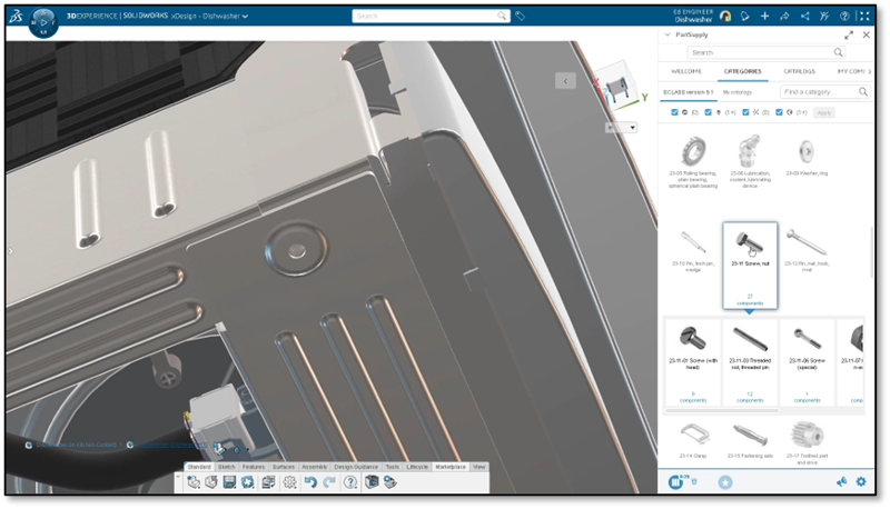
PartSupply Integration – speed up your workflow by accessing and adding standard parts right from a side panel on the 3DEXPERIENCE platform.
Easily access components from PartSupply, the free online parts catalog with ready-to-use, sourceable 3D parts/components, right from your design session using the content side bar.
Accelerate your workflow for creating assemblies by choosing from a library of standard parts from 1,700 providers that can be reused across all your design projects and assemblies, such as fasteners and brackets.
Zoom in Entities – accelerate your design process by zooming to selected entities.
There’s a new command called “Zoom in Entities” available from the selection field within any command. Zooming into the selected entities allows you to easily focus on that part of the design you are working on.
PART & ASSEMBLY DESIGN
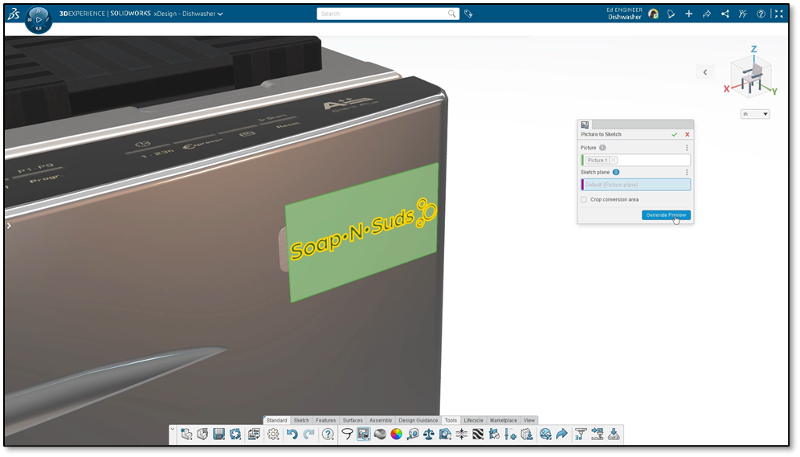
Convert Image to Sketch – convert images to editable sketches for multiple use cases.
Seamlessly convert images into editable 2D sketches with the “Picture to Sketch” tool. This can be useful for several cases. For instance, if you are working with a logo on an appliance, as pictured below, you can convert the edges of that logo to a sketch. From there you can do an extrude cut so you have a plate with the logo on it on your design. You could also use it if you had a hand sketch and you wanted to create features based of that. It’s certainly easier than tracing it with Sketch Entities as you can use the Picture to Sketch feature to automatically create a sketch based off your image.
It can also be useful if you’re converting screenshots of 2D or other CAD systems to migrate to a 3D CAD system as you could easily convert those sketches.
Session Information Panel – instantly pinpoint components imported “as reference.”
Easily identify which components were imported as a Reference into your assembly from the Session Information panel. For instance, any standard component you bring in from PartSupply will be inserted as Reference, meaning it’s read only and any change that the provider of the part makes will be updated to the instance of that part in your design.
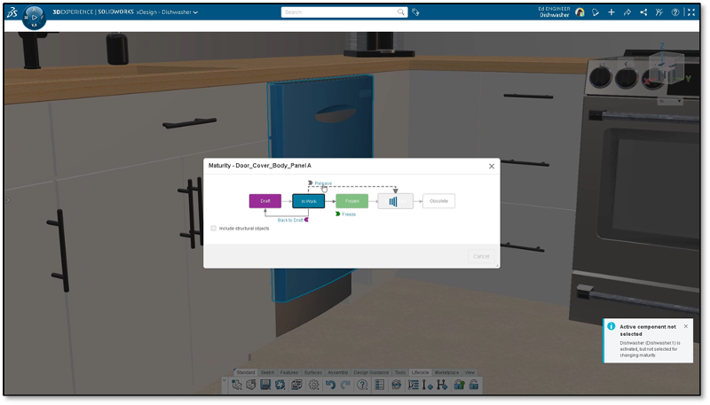
Manage Design Lifecycle – change the maturity state of a component on the fly to efficiently manage and update status throughout the lifecycle.
There’s a new enhancement for managing the design lifecycle that lets you easily change the maturity state of any selected component. When you’re working on an assembly, and you just made a modification to a component in that assembly, and you want to change the maturity state you don’t have to activate the component. If it’s selected, you can change the maturity state of that component.
FREEFORM DESIGN
Cancel all Changes – save time testing out design iterations and easily get back to a desired starting point.
For those of you doing digital sculpting and freeform modeling there’s a new feature called “Cancel Subdivision” that undoes all of the changes made to the subdivision model since you last clicked Edit Subdivision instead of having to hit undo several times to get back to a desired shape.
Just exit the Edit Subdivision mode by hitting Cancel Subdivision on the mode bar at the top of your screen.
Extrude Mesh – save time on clicks when selecting faces and extruding.
Ensure your selections stay selected after you do an extrude by enabling the Extrude Mesh and then clicking the “Repeat Selection”
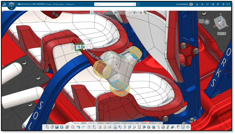
Triangle Priority Symmetry – easily create symmetry on high-valence vertices.
With the new Triangle Priority option, you can create symmetry on high-valence vertex areas on shapes where multiple edges meet at one vertex, such as cylinders and globes.
Manufacturing Definition
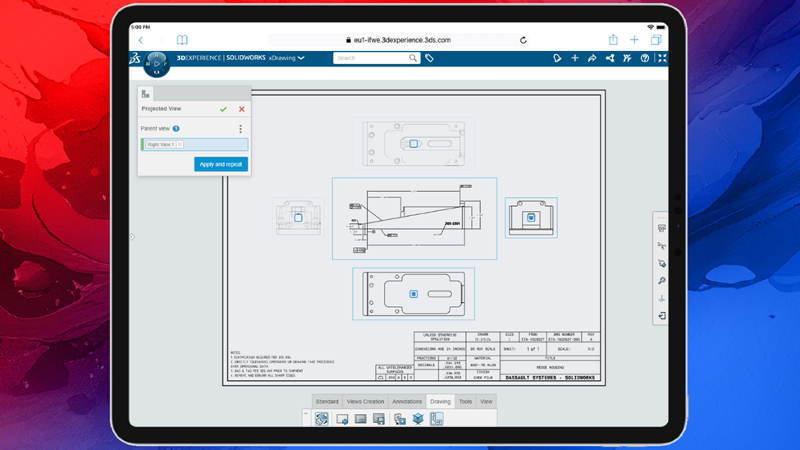
For those of you working with definitions, we’ve got you covered on your touch devices as you can utilize all the projection views available and easily toggle the views to turn them on and off. These views include first angle and third angle so you can easily meet standards and provide the necessary views. Also, when you are creating the projection views if a view is not selected it will be displayed transparently alerting you to select one.
SHEET METAL DESIGN
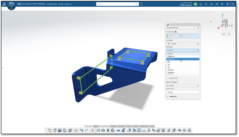
Hole Command – Reduce human error, speed up your design process and ensure accurate, standard hole sizing.
Last, but not least, for the sheet metal designers, there is now a Hole feature so you can easily create standardized holes and eliminate the need for those pesky hole tables. Using the new single, easy-to-use command you can choose from a wide variety of industry standard hole types and sizes, ensuring your design fits together correctly the first time. We have even included popular sheet metal specific standards, such as PEM.
That’s a wrap for this update but stay tuned as we’ve got lots more in the works. To see the last update check out this blog.
Also, if you haven’t got your hands on the browser-based tools and want to expand your toolset check out the SOLIDWORKS Cloud Offer at https://SOLIDWORKS.com/cloud.


