
First off, I want to say how great it was to reunite with everyone at this year’s 3DEXPERIENCE® World user event after three years! I hope you caught my hands-on session on 3D Motion Creator. If not, here’s your chance to see what’s new. Long story short- lots! Today I want to discuss what’s new in the R2023x GA release.
For those of you who don’t know, 3D Motion Creator is a browser-based tool for kinematic and dynamic analysis that enables users to see how their models will behave in the real-world. It enables users to directly prepare a motion simulation for kinematic analysis based on existing 3D designs by selecting products, parts, or engineering connections, such as mates. Plus, because 3D Motion Creator runs on the 3DEXPERIENCE platform, you also have data management and collaboration functionality so you can collaborate with your colleagues and keep everyone up to date, including managers and suppliers.
This release enables you to run dynamic simulations more easily, visualize applied loads and motion drivers through arrows and define independent body structures. I will discuss in more detail below.
- Upgrade or Duplicate xDesign Mechanism – more flexible options to run advanced motion studies on your parametric model mechanisms.
You can now use an existing mechanism from 3D Creator and run advanced motion studies on it in 3D Motion Creator. You can choose whether to upgrade the mechanism in 3D Motion Creator or duplicate it to run the advanced motion studies and keep your original 3D Creator mechanism in addition to the duplicate.
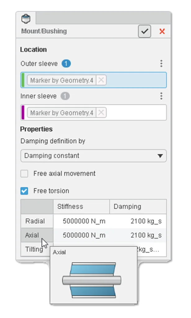
- Cylindrical Bushing Command – simplify your rubber bearing modeling process for general mechanisms.
You can now define a machine element type for cylindrical bushings to evaluate elasticity by linear stiffness and damping. This functionality also introduces compliance in joints for dynamic analysis to accurately cover real-life behavior and correctly assess loads in the joints.
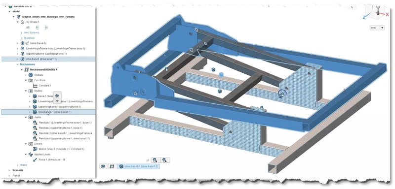
- Visualization Symbols – quickly localize and identify motion elements in your 3D view.
You can now see visualization symbols for various motion elements, such as bodies, drivers, and applied loads. You can use motion visualization symbols to select symbols on-screen and interact with the symbols in the graphics area. For example, you can select a motion joint to define a motion driver on that joint. You can select a symbol to find the item in the Feature Tree. To hide and show the visualization symbols use the View Options command in the action bar.
- Cross-highlighting and Reference Elements – identify your selections faster.
Whatever you select in the 3D view will be highlighted in the Feature Tree and vice versa. So, if you select a part in your Feature Tree, it will be highlighted in the model.

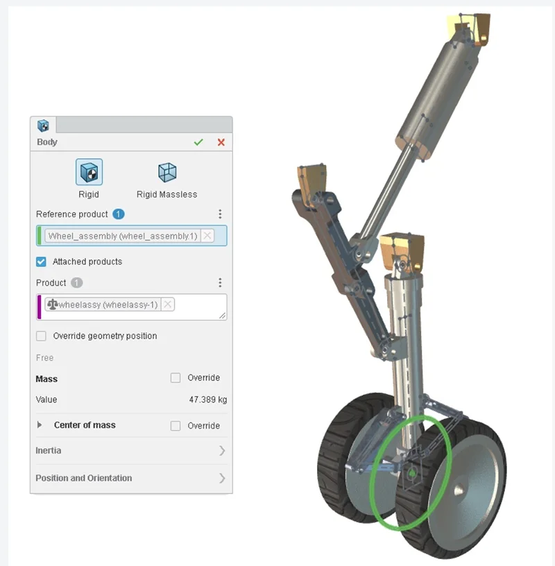
- Products Attachment/Dress Up – enable workflows that drive assemblies downstream.
Easily attach 3D geometry, such as a wheel, to existing bodies and run a simulation on it to see how it will contribute to the mass properties of the body. This is also known as “Dress up” functionality, which was introduced in CATIA for doing relational design with motion simulation. For example, many OEMs in the aerospace and automotive industries work with skeleton models of their key mechanisms, which can be both 2D and 3D wireframes.
SOLIDWORKS® also uses a similar concept called Master Layout Sketch to drive assemblies downstream. Essentially, what this functionality does is enable you to run motion simulations on the skeleton models to make sure the mechanism works in the best possible way.
- Mechanism Drivers in Kinematics Player – assess kinematic behavior faster.
Clearly separate out the degrees of freedom driving the mechanism, name them accordingly, and create a clear view based on them in the kinematics player to assess the kinematic behavior of the system.
That’s a wrap for this round. Let me know what you think in the Comment section and stay tuned for the next update coming soon.
To learn more, check out my last couple of blogs:
./brands/solidworksblog/2021/10/what-is-3d-motion-creator.html