How to Build a Data-Centric Manufacturing Operation
Learn how to move away from scattered data towards a resilient, data-centric operation to cut...
July 13, 2026
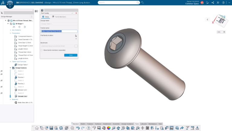
What’s New in SOLIDWORKS xDesign R2026x FD03: How...
In SOLIDWORKS xDesign R2026x FD03 you can now create and manage part families from a...
July 10, 2026

Deaton Engineering: Advanced Design Consultants That Get to...
SOLIDWORKS helps Deaton Engineering move faster from requirements and concepts to validated, production-ready designs.
July 8, 2026
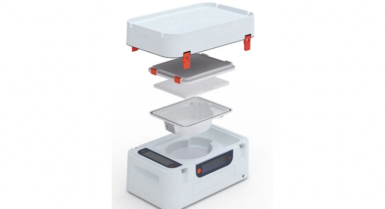
ScubaTx Designs for the Realities of Organ Preservation
Medical equipment manufacturer uses SOLIDWORKS to develop organ preservation technology while managing design data, simulation,...
July 7, 2026
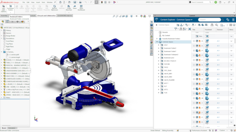
Spend Less Time Looking for Data and More...
The Content Explorer is a simple web-based interface similar to Windows Explorer that can be...
July 1, 2026
Mastering the Art of Nesting in Manufacturing
Discover the transformative power of nesting software in streamlining manufacturing processes and enhancing efficiency.
June 30, 2026
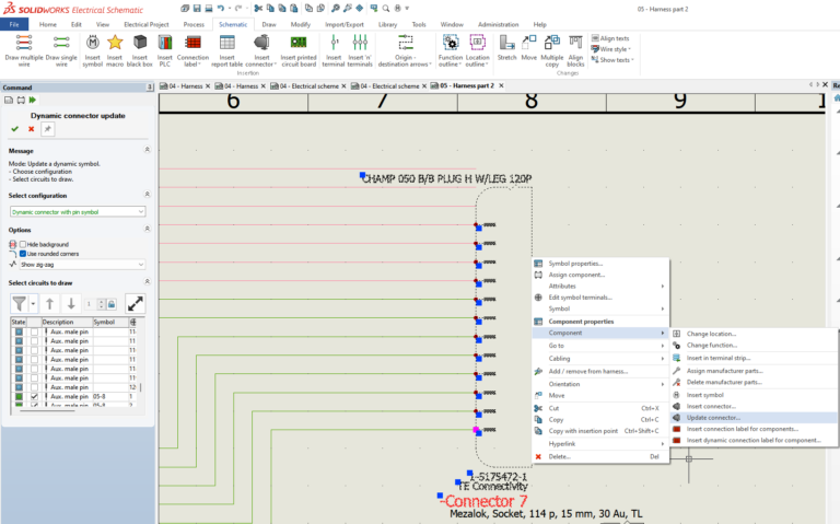
SOLIDWORKS Electrical: Precision Engineering for Large-Scale Connector Management
With new functional updates that introduce structural enhancements to the Dynamic Connector toolset, your workflow...
June 29, 2026
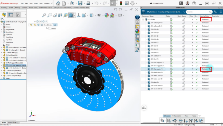
Change Management with SOLIDWORKS Design: Part 2
Learn how to use change management in SOLIDWORKS Design in five steps in part two...
June 26, 2026