

Hello to all,
Welcome to the new edition of the SOLIDWORKS® Support Monthly News! This monthly news blog is co-authored by members of the SOLIDWORKS® Technical Support teams worldwide. Here is the list of topics covered in this month’s Blog :
-
SOLIDWORKS® Simulation: Add a small tolerance to Interaction gap range values
-
Mastering Tooltips in SOLIDWORKS® : A Guide to Efficiency and Precision
-
Resolving error message, “Process stops because some file have reference outside the selected folder”, when using Batch Save to 3DEXPERIENCE.
1. SOLIDWORKS® Simulation: Add a small tolerance to Interaction gap range values
– Jay SEAGLAR
When you mesh a model in SOLIDWORKS® Simulation, the output is an approximate (tessellated) representation of CAD geometry. The image below shows an exaggeratedly coarse mesh to make this more obvious:
When you subsequently run a SOLIDWORKS Simulation study, the solver uses the meshed representation of the model for its calculations… not the original CAD geometry representation. If your study includes interactions like Bonded (meshed independently), Contact, or Virtual Wall, the solver creates special relationships between portions of the mesh to enforce those interactions.
To create these relationships, the solver must calculate distances between mesh element faces and/or nodes. One reason it does this is to properly consider user-defined values of Gap range for bonding or Gap range to consider contact when forming interactions.
The out-of-the-box default value usually ends up being a small (but non-zero) value relative to the dimensions of the model. You should always check the Gap range value because in many cases it requires adjustment to get the study to behave how you want. For a Bonded Interaction, it should be just large enough to comfortably bond what you want, but not so large that it bonds too much. The same concept applies to Contact Interactions.
An important point to keep in mind is that as a general rule, you should use a slightly larger value than the size of the geometry-based gap that you wish to include. If the largest gap you want to bond measures 20mm in your CAD model, to ensure proper enforcement of this bond, use a gap range slightly larger than 20mm, in most cases probably somewhere between 20.0001 and 22mm. To verify the areas of interactions (such as Bonded, Contact, Free, etc.), use the Interaction Viewer, ideally before you run your study.
TIP: To learn how to use the Interaction Viewer effectively, see topic “Use the SOLIDWORKS® Simulation Interaction Viewer to see bonding locations” in the September 2022 Edition of the “SOLIDWORKS® Support Monthly News” blog.
BUT WHY?
This is necessary because the solver implements the interactions based on coordinates of the mesh, not based on coordinates of the CAD geometry. This point bears repeating, so to put it another (somewhat dramatic) way: the solver is oblivious to CAD geometry measurements. Because the mesh is a tessellated representation of the geometry, the precise distance calculated between mesh coordinates depends on many factors including the element size, orientation/alignment, curvature, the type of element (draft or high quality), etc.
ZERO GAP RANGE EXAMPLE
Consider a simple model with two touching (coincident/tangent) cylindrical faces. The top body has a small prescribed displacement to pull it up, and the bottom body has a fixed restraint.
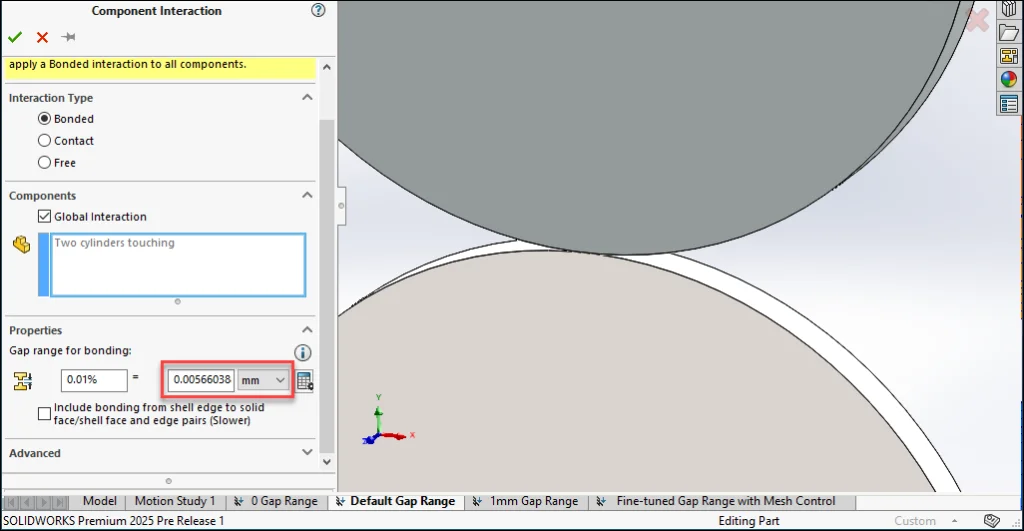
Let’s see what happens if we define a 0mm Gap range for bonding. Notice a message in an information ⓘ tooltip with text:
Increase the specified gap range by a small tolerance to ensure proper enforcement of this interaction. Use the Interaction Viewer to verify the interactions.
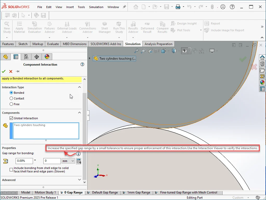
This tooltip message is one of the User Interface (UI) improvements that the R&D team implemented in SOLIDWORKS Simulation 2024 to raise awareness of this behavior and to provide appropriate guidance.
The classic mistake here is to think that because the minimum distance between these two bodies is 0.000000mm in the CAD geometry, a Gap range for bonding of value of exactly 0mm will always produce the expected bond. As explained earlier, the solver may evaluate that the distance between the mesh element faces/nodes is not exactly zero. It may be a small value (non-zero) value instead. This is especially likely for (though not unique to) curved geometry.
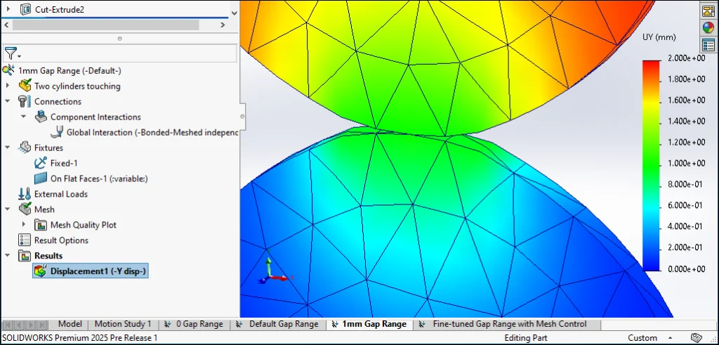
Running this study and subsequently viewing a displacement plot confirms that the bodies did not get bonded.
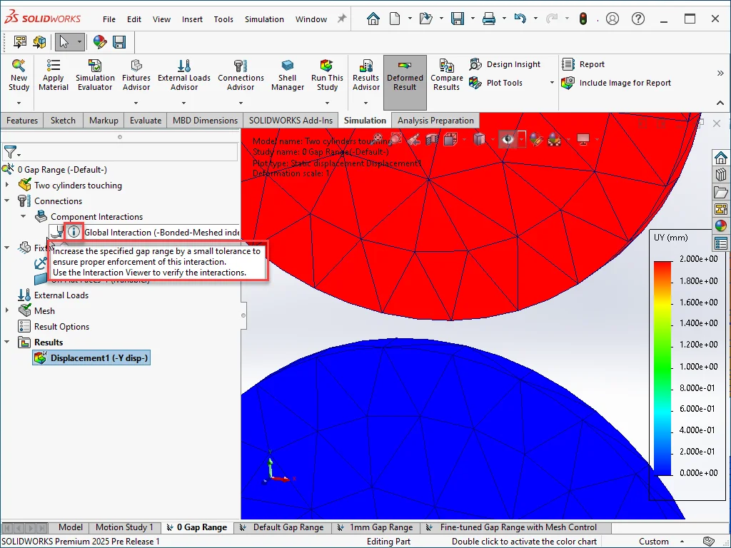
Notice
Information

tooltip appears next to the left of the Interaction name in the study tree. The tooltip in the study tree appears only for 0mm gap range values, while the tooltip inside interaction PropertyManagers always appears – more on the reasoning for that later.
DEFAULT GAP RANGE EXAMPLE
What will happen if instead of a 0mm Gap range for bonding, we use the default value (0.00566038868mm in this case)?
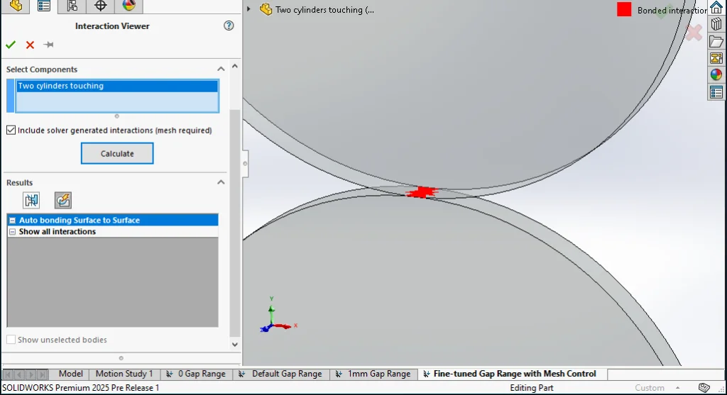
This time, instead of running the study, let’s use the Interaction Viewer.
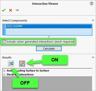
In case you didn’t read the aforementioned blog topic about the Interaction Viewer, here’s something you must not overlook when using the tool in this context:
- Be sure the study has an up to date Mesh.
- Turn on the Include solver generated interactions (mesh required) option.
- Click Calculate.
- IMPORTANT: Hide Geometry Based Interactions by turning OFF the toggle button on the left.
- Be sure that Solver Based Interactions are shown (turn ON the toggle button on the right if needed).
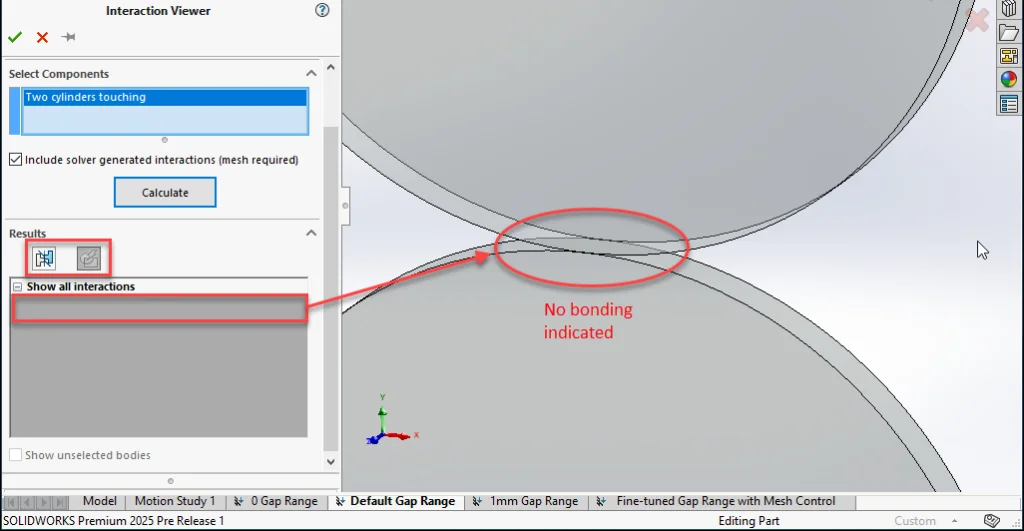
With only Solver Based Interactions showing, we see that there will not be any bonding. Sure enough, if you run the study, the results are identical to the 0mm gap range study (bodies move apart freely).
It may seem trivial to suggest the Interaction Viewer here instead of just running the study because in this simple example either step takes about the same amount of time. However, keep in mind that using the Interaction Viewer has the following advantages, especially for a more complex/real-life model:
- The more areas there are with interactions, the harder it becomes to detect a problem which may be very localized (small region especially if the overall model is large) based only on study results.
- The time it takes to run a study (especially if it has many components and Contact interactions) can be significantly longer than using the Interaction Viewer.
- If the study setup is unstable (lack of Bonding or proper Contact are common possible reasons), the study may eventually fail to solve. When this happens, you may feel frustrated that you spent hours watching painfully slow solver progress, only to see that the study ultimately failed to converge and you have no useful results.
A (POSSIBLY) TOO LARGE GAP RANGE EXAMPLE
Avoid setting a gap range value that is too large. For Bonding, an excessively large value risks “over-bonding” – either an area that is too large compared to what would happen in real life (which can over-stiffen the model), or the formation of bonds between entities which you intend to remain Free.
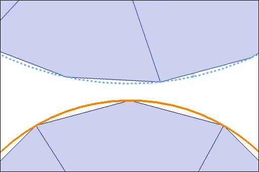
Here’s what the Interaction Viewer shows with a Gap range for bonding of 1mm:
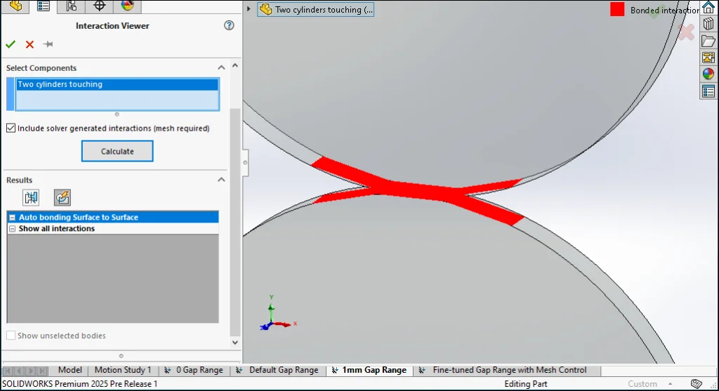
Clearly, the area getting bonded extends much further away from the very small region where the cylinders touch (which is actually an edge in the CAD geometry). For the purposes of this example, let’s imagine that you want to represent the effect of a very small amount of adhesive between the two cylinders. Therefore, the bond should not extend far away from the common tangent edge (if instead you wanted to represent a weld bead, perhaps a bonded area this large would actually be desirable).
A displacement plot reflects this bonding pattern.
TIP: Animate the plot for an even better visualization of the effect of the bond.
A “JUST RIGHT” GAP RANGE EXAMPLE
Before we look at what a “not too small and not too large” gap range value might be for this specific study, it’s good to remember that the element size in the region of the interaction has a significant impact on the behavior. In general, an element either does or does not get included, depending on some calculation done by the solver using coordinates which represent that element. This means that if you have a coarse mesh, a small change to the gap range value can have a massive effect on the area that gets bonded. Therefore, by selectively adding Mesh Controls, you can make your interactions behave more predictably (just don’t over-refine your mesh because that can introduce other problems).
This also explains why you many sometimes see that a zero Gap range for bonding produces the bonding that you want, but as soon as you change something (mesh settings, dimensions of model, etc.) the behavior is different.
After refining the mesh a bit, here’s what the Interaction Viewer predicts with a Gap range for bonding of 0.005mm
Some further tweaks might be beneficial, but already the results look much closer to what we would expect in real life (if representing a very small amount of adhesive for example):
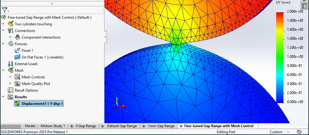
If you are a particularly astute reader, you might have noticed that this gap range of 0.005mm is actually smaller than the default gap range value of ~0.0057mm which we looked at earlier. This serves to reinforce the previously made point that element size is a major factor in the behavior of interactions because it affects the distance calculations between mesh coordinates.
IS A ZERO GAP RANGE VALUE A SPECIAL CASE?
No, gap range values of zero are actually not a special case. The same behavior and guidance applies to any value of gap range. The only way in which a zero gap range value differs from other values is that it is immediately identifiable as likely problematic. This is because with a value of zero, it is evident (independently of geometry) that no “small tolerance” has been added to slightly increase the gap range value. Recall the text from the aforementioned tooltip:
Increase the specified gap range by a small tolerance to ensure proper enforcement of this interaction. Use the Interaction Viewer to verify the interactions.
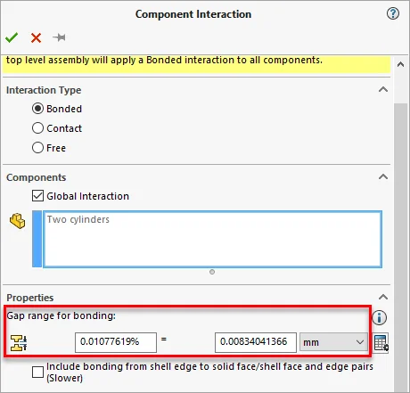
This is why when assessing a study with misbehaving interactions, one of the first things the R&D team will check for is zero gap range values for any interaction. If there aren’t any, they will move on to measuring distances between bodies. The SOLIDWORKS Measure Tool is a good starting point, but remember that it is based on CAD geometry coordinates – not the mesh which is what the solver uses. For Bonding, the Calculate minimum gap (Component Interaction) or Show the suggested gap range (Local Interaction) buttons automate this somewhat, but you should still check the value and add an appropriate tolerance.
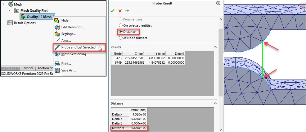
Using Probe > Distance on a Mesh Quality Plot to see distance between nodes can give you a slightly better idea about the effect of mesh tessellation, but remember that the solver generates either Surface to Surface or Node to Surface interactions – not Node to Node interactions. Therefore, even if the distance between a pair of nodes falls within a certain value, this is not necessarily the value that the solver references when it generates bonds or contacts.
Returning to the previous example, consider that the two cylindrical faces are instead 2mm apart, and the setup is a bit different: instead of using a Bonded Interaction, we’ve defined a Contact Interaction. In addition, we’ve reversed the direction of the prescribed displacement to push the top cylinder down enough to close the gap. This will cause it to come into contact with the bottom cylinder, and create some deformation from the contact pressure.
If you set the Gap range to consider contact to a value of 2mm, depending on the previously discussed factors, the solver could evaluate the distance between the element faces as 1.99mm or 2.01mm. In the latter case, with a Gap range to consider contact value of 2.000mm, you would see the bodies passing through one another (interfering) instead of touching and showing non-zero stress values. This is why you need to make the Gap range to consider contact slightly larger, use the Interaction Viewer, make adjustments to mesh and gap range, use the Interaction Viewer again (repeating this process as needed).
BUT… HOW MUCH OF A “TOLERANCE” SHOULD I ADD TO THE GAP RANGE?
There is no definitive rule because as explained previously, the value is relative to the dimensions of the geometry included in the study, element sizes, proximity of other components, etc. The key point is that the when used together, the following give you precise control over how your study will behave:
- Ability to specify an exact Interaction Gap range value
- Ability to validate Interactions using the Interaction Viewer
For additional details and nuances, refer to QA00000125543: In SOLIDWORKS® Simulation, what is the logic behind the behavior of the ‘Gap range for bonding’ option?
Finally, don’t forget about other useful tools at your disposal like the Underconstrained Bodies tool. In situations where the results of the Interaction Viewer are visually very “busy” (many shaded regions possibly including some within cavities or otherwise difficult to see), the Underconstrained Bodies lets you quickly identify bodies that are “flying away” from the rest of your model… perhaps due to a Gap range for bonding value that is too small.
To learn more about the Underconstrained Bodies tool, see topic “Saving time with the improved Underconstrained Bodies tool (new in SOLIDWORKS® Simulation Professional & Premium 2023)” in the April 2023 Edition of the “SOLIDWORKS® Support Monthly News” blog.
2. Mastering Tooltips in SOLIDWORKS® : A Guide to Efficiency and Precision
– Jayendra POTDAR
In the realm of SOLIDWORKS® design software, where every click and detail matters, efficiency is key. One of the often-overlooked yet immensely powerful tools in SOLIDWORKS is the Tooltip feature. This unassuming feature provides quick access to crucial information about parts, assemblies, and features, significantly enhancing productivity and accuracy in design workflows.
Let’s explore the Tooltip Feature:
- What is Tooltip?Tooltip in SOLIDWORKS is a contextual information display that appears when you hover your mouse pointer over a part, assembly, feature, or dimension within your design. It offers concise details such as dimensions, properties, material specifications, and custom notes without needing to open the files separately.
- How to Activate Tooltip?Activating and using tooltips in SOLIDWORKS is straightforward:
- Simply hover your mouse pointer over the desired element – whether it’s a part, assembly component, feature, or dimension.
- A small window will appear near your mouse cursor displaying information about that specific element.
- What is the Use of Tooltip?The primary uses and benefits of tooltips in SOLIDWORKS include:
- Instant Information Retrieval: Quickly access critical details about parts or assemblies, such as Materials, Weight, etc.
- Enhanced Productivity: Reduce the time spent navigating through properties dialogs or searching for specific information manually, as they provide immediate answers at your fingertips.
- Efficient Collaboration: Facilitate clearer communication among design teams by ensuring that everyone has access to accurate and up-to-date information about design elements
Example: Utilizing Tooltips for Custom Properties
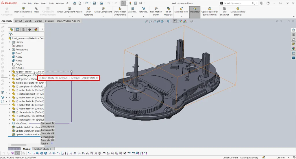
Let’s say you’re working on an assembly, each with specific custom properties like Material, Weight, Part number, etc. Instead of opening each part individually to check these properties, you can leverage tooltip and have a quick glance at the components with the applied filter:
- Search Filter in FeatureManager Design Tree: Use the search filter to locate parts based on specific custom properties. For example, search for ’Material’ to find all parts where this custom property is used.
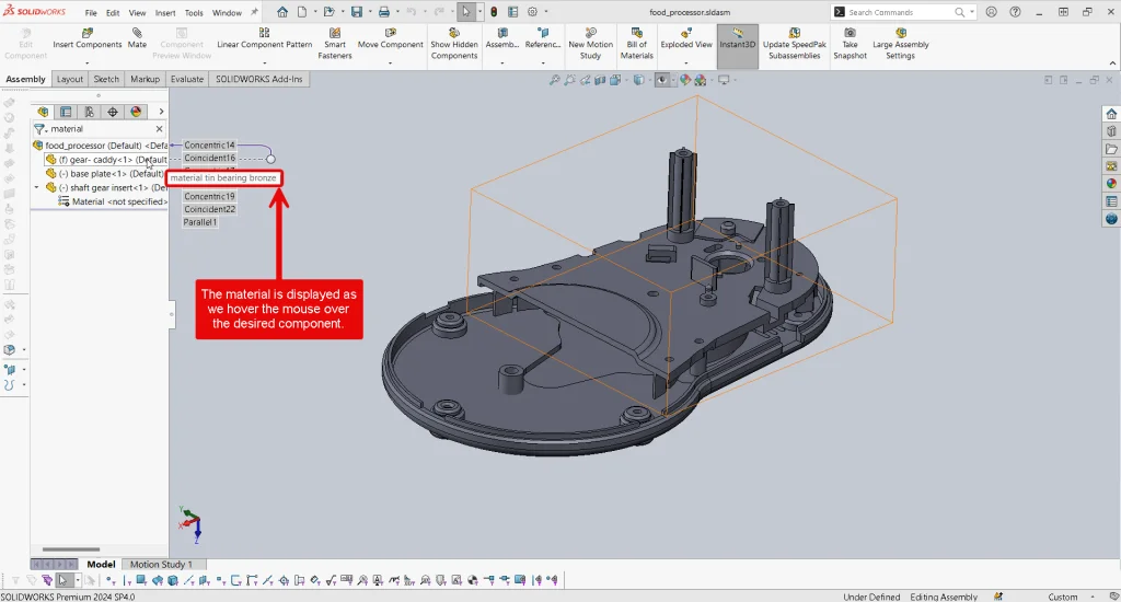
- Tooltip Usage for Custom Properties:
- Hover over each part in the FeatureManager Design Tree. The tooltip will display essential information, including custom properties like ‘Material’, directly within the assembly context.
- This capability allows you to gather necessary data swiftly without disrupting your workflow, ensuring efficient management of large assemblies.
Additional tip:
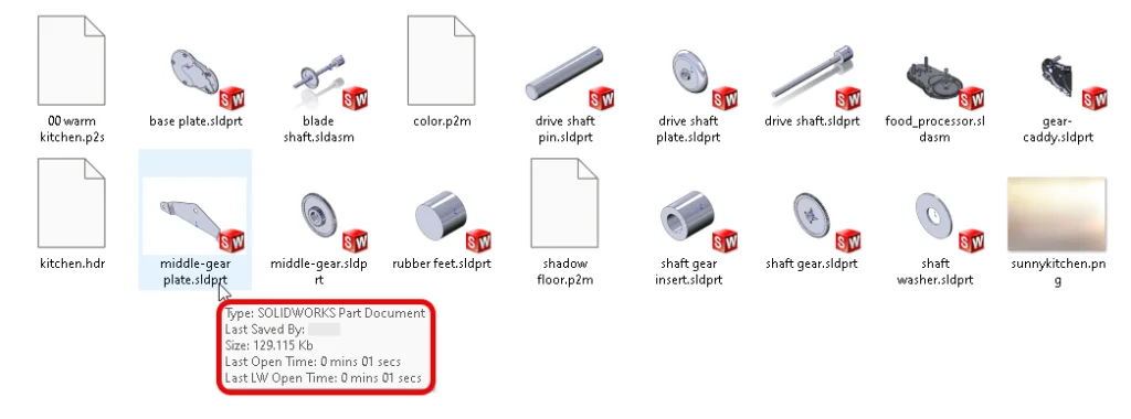
For SOLIDWORKS files specifically, tooltips in File Explorer can be particularly useful. When you hover over a SolidWorks file (such as a .sldprt for a part, .sldasm for an assembly, or .slddrw for a drawing), the tooltip might display:
- File Name: The name of the SolidWorks file.
- File Type: The extension (e.g., .sldprt, .sldasm, .slddrw).
- Size: The size of the file.
- Date Modified: The last time the file was modified.
You can find more information in this SOLIDWORKS Web Help.
You can also refer the following QA article:QA00000118913 :[How do I display a tooltip for SOLIDWORKS® files in Windows® Explorer?]
Maximizing Your SOLIDWORKS Experience with Tooltips:
In conclusion, tooltips in SOLIDWORKS represent a powerful tool for enhancing productivity, improving data accessibility, and fostering seamless collaboration among design teams. By mastering the use of tooltips, designers can streamline their workflows, reduce errors, and achieve higher levels of efficiency in their design processes.
Whether you’re a seasoned SOLIDWORKS user or exploring its capabilities for the first time, incorporating tooltips into your workflow will undoubtedly elevate your design experience.
Stay tuned for more insights and tips on optimizing SOLIDWORKS functionality!
Happy designing!
3. Resolving error message, “Process stops because some file have reference outside the selected folder”, when using Batch Save to 3DEXPERIENCE.
– Bhavya JHAVERI
When using Batch Save to 3DEXPERIENCE, you may encounter the error “Process stops because some files have reference outside the selected folder.” This error occurs when the reference files for an assembly are located outside the folder of the main assembly you’re trying to upload.
During the Batch Save operation, a ‘save.xml’ file is generated at C:Users<username>AppDataLocalDassaultSystemesBatchSave<username>. The error message will specify the file path of the assembly and its external references.
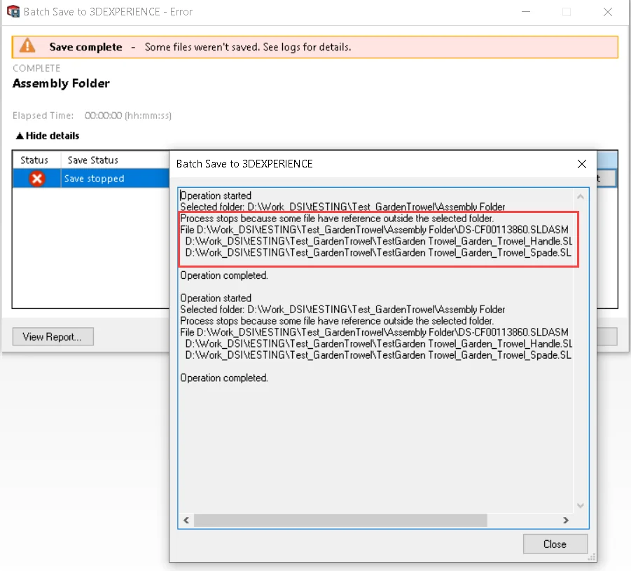
Error: “Process stops because some files have reference outside the selected folder.
File <File path of assembly> has external reference:
<File path of references>”
Resolution: To resolve this issue, enable the “Include referenced files located outside the selected folder(s)” option in the Batch Save to 3DEXPERIENCE dialogue box. This will allow you to upload the file along with its referenced files, even if they’re located outside the selected folder.
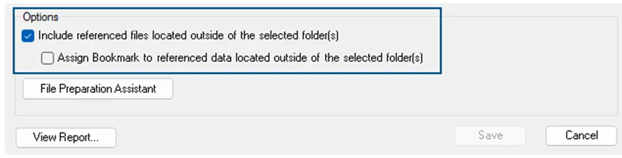
If you need the referenced part files and their assembly to be present in the same bookmark on the platform, also enable the Assign bookmark to referenced data located outside of the selected folder option in the Batch Save to 3DEXPERIENCE dialogue box. This option is available in Design with SOLIDWORKS and SOLIDWORKS Connected applications from version 24x FD02 onwards.
For more details refer help: Saving Multiple SOLIDWORKS Files to the 3DEXPERIENCE Platform
Saving Multiple Files in 3DEXPERIENCE (Refer Section Saving Data Using the Batch Save to 3DEXPERIENCE Command)