

Hello to all,
Welcome to the new edition of the SOLIDWORKS® Support Monthly News! This monthly news blog is co-authored by members of the SOLIDWORKS® Technical Support teams worldwide. Here is the list of topics covered in this month’s Blog :
- Saving time with the improved Underconstrained Bodies tool (new in SOLIDWORKS® Simulation Professional & Premium 2023)
- Controlling multiple parts using the single sketch
- Custom Appearances in SOLIDWORKS® Visualize – A case study
- Why does the last used BOM template not remembered while inserting a new BOM, instead it always uses standard BOM Template?
1.Saving time with the improved Underconstrained Bodies tool (new in SOLIDWORKS® Simulation Professional & Premium 2023)
– By Jay SEAGLAR
An unstable study setup is perhaps the most common reason why a study fails to solve. When this occurs, you might see an error message like “The solver has numerical difficulties” or in some cases an exception code with a SIMSTACK.dmp file because the solver ended abnormally. The instability often stems from mistakes or oversights in the study setup. For example, forgetting to apply a fixture to a component, or perhaps some issue with interaction definitions between components.
The Interaction Viewer is very helpful for diagnosing problems with bonding or contact (see article “Use the SOLIDWORKS® Simulation Interaction Viewer to see bonding locations” in the September 2022 Edition of the “SOLIDWORKS® Support Monthly News” blog).
However, what if you already checked the Interaction Viewer and everything looked fine? There are “classic” instability troubleshooting techniques like the Use soft spring to stabilize model option, or systematically excluding certain bodies from the study to isolate the problem. These techniques can be quite tedious though – especially for more complex study setups where trial and error methods are not efficient.
This is where the new, improved version of the Underconstrained Bodies tool really shines (take a look at this short video for a quick demo).
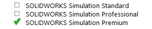
This improved version is available for static studies in SOLIDWORKS® 2023, but only with SOLIDWORKS® Simulation Professional and SOLIDWORKS® Simulation Premium licenses. Do not be deceived – although how you access and use the tool seems similar to previous versions (or what you get with SOLIDWORKS® Simulation Standard), under the hood, it is an entirely different and much more powerful and efficient algorithm. Visually, its most impressive feature is probably how unambiguously and realistically it can animate free movements of a body (or group of bodies which move together).
In a recent support case on a complex model, this tool proved much faster than a “classic” trial and error instability troubleshooting approach. The static study in question was an assembly with about 40 bodies. This may not seem overly complex, but consider that the study had more than 70 bolt and pin connectors and close to 100 interactions defined. The mesh was also fairly dense, with over 1 million nodes making for just over 3 million Degrees of Freedom (DOF).
Here is the troubleshooting approach that revealed the problem within minutes:
- Load the SOLIDWORKS® Simulation Add-In using a SOLIDWORKS® Simulation Professional or SOLIDWORKS® Simulation Premium license.
- Copy the existing study.
- In the copy of the study, change the mesh for all bodies from High Quality to Draft Quality elements (to expedite troubleshooting).
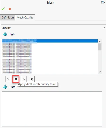
- Mesh the study.
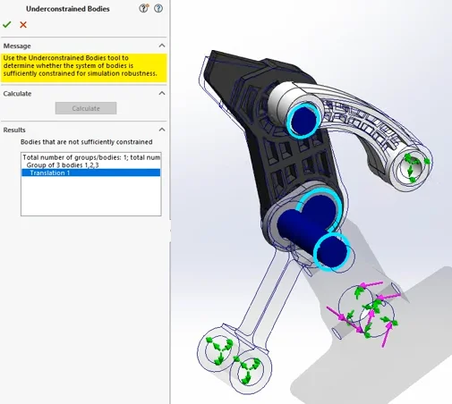
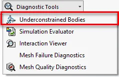
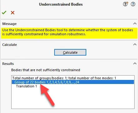
- In the study tree, go to Connections > Underconstrained Bodies (or use the new Diagnostic Tools Simulation CommandManager button) and click Calculate.
- Observe that there is one free mode listed, composed of a group of 22 bodies which move together. Click on the group to highlight the offending bodies in the SOLIDWORKS® graphics area.
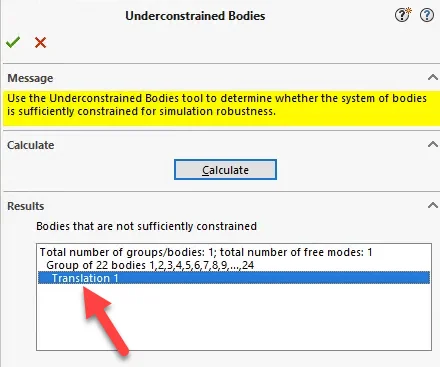
- Click on Translation 1 to animate the movement of this group of bodies relative to the rest of the model.
- Close the Underconstrained Bodies tool. In the SOLIDWORKS® graphics area, click on a body belonging to the aforementioned group to highlight the body in the study tree. Ideally, choose the body that connects the offending group to the remainder of the model.
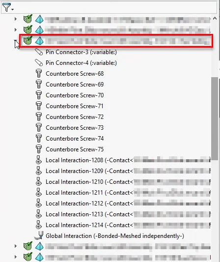
- Expand the study tree and review any study definitions which include geometry from the body of interest. The animation of the free mode above is likely to help you narrow down a prime suspect or two (especially if you are the one who defined the study).
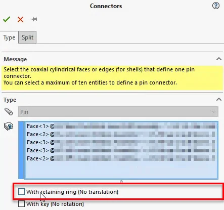
- In this case, review of the two pin connectors in which this body participated immediately revealed a mistake in the setup. Considering the design/analysis intent, both pin connectors should have had the With retaining ring (No translation) option active. However, the checkbox was unintentionally cleared for one of them (allowing a completely unrestrained sliding of a group of bodies), which caused the solver to fail due to instability.
As soon as this mistake in the study setup was corrected, running the study again (initially still with a Draft Quality mesh in case there were other problems requiring further troubleshooting) resulted in a successful solve. This set the stage for making some additional tweaks before running with a High Quality mesh for examination of final results.
Be sure to keep the improved Underconstrained Bodies tool in mind the next time you suspect some instability in your study setup – it could save you from individually having to review each of your connectors… and possibly suffering finger fatigue from all that clicking!
2. Controlling multiple parts using the single sketch
-By Nikhil BHIRUD
When you are working on assembly, a small change in one part requires multiple related components to change. This requires quite a time. In this blog, we will see how we can use single sketch to create and control multiple parts to reduce the efforts to individually update the parts each time.
Let’s get started!
- Creating the master sketch & master part file : In this example, we will create an assembly for the table using single sketch which we will call a master sketch. The master sketch contains the rectangular outline along with the profiles which are required to create respective parts. We will extrude the inner contour of the master sketch to construct the rectangular table top with the cut outs to fit the parts. Once finished, this part will serve as the master control file
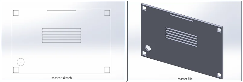
- Creating multiple parts from master sketch: In order to control the parts with master sketch, we will need to have a way to link them to the master sketch. This is where the Insert Part command in SOLIDWORKS® will come in handy.
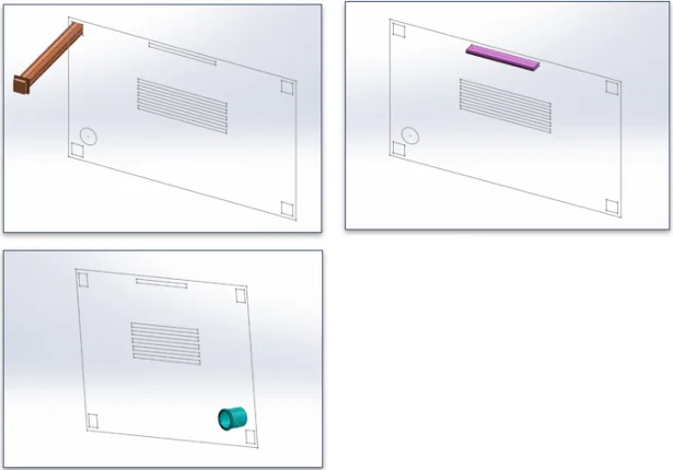
- Create new part.
- Go to Insert > Part > select Master part file
- Insert Part PropertyManager > Check the options Absorbed sketches and Unabsorbed sketches.
- This will bring master sketch into the new part in its original form. Use this sketch to create the part and do the necessary modifications. Repeat this process for every part. Once the parts are created, we will insert them into a new assembly.
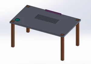
- Creating assembly from parts : Now, once we are ready with all the parts we need to create table assembly. Let’s add all these parts into new assembly and create the model for table.
- Controlling the parts with the master part Sketch/file: As we have all the parts linked to the master sketch, We can edit the master sketch and make the changes in master file. The part affected by the change will update automatically. As an example I have changed the size and location of the cutouts/profiles in master file. The parts and the assembly are updated automatically.
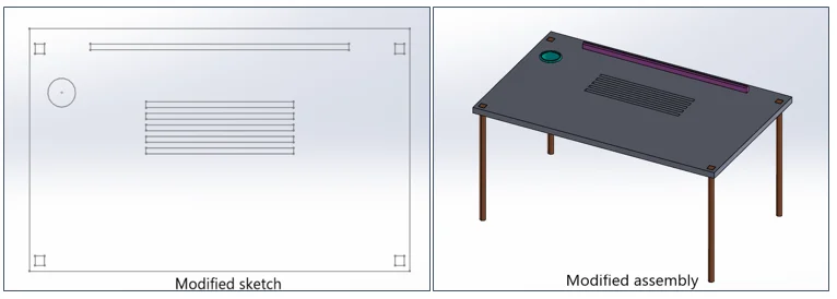
Note: The mates given in the assembly may require the manual editing for missing references depending upon the change done.
3.Custom Appearances in SOLIDWORKS® Visualize – A case study
– By Camille JOHNSON
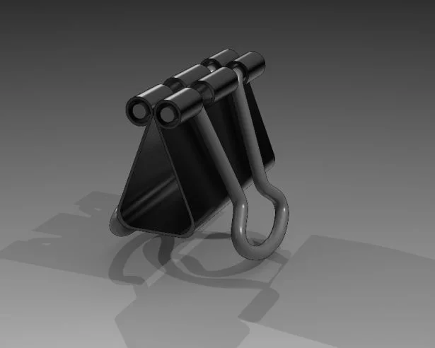
I always have odds and ends sitting on my desk at home and in the office. I picked up a binder clip the other day to see if it was possible to quickly make in SOLIDWORKS®. Indeed it was, but then I was set on creating a really cool rendering in SOLIDWORKS® Visualize Professional.
In this post, I’ll walk you through creating a custom appearance in SOLIDWORKS® Visualize Professional. That’s the main objective of this blog post. I’ll also do a quick camera set up and add a few final touches to achieve the rendering seen below:
Before I start, this case study in making a custom appearance does require a pre-made SOLIDWORKS® CAD model. I, of course, will be using the binder clip, but feel free to create something that is sitting on your desk. A pen or a pencil, perhaps, or challenge yourself with something like a pair of blue light-blocking glasses. I am pretty convinced everyone uses those these days, as we all sit at our computer screens.
I will start by creating a new project and importing my CAD model into SOLIDWORKS® Visualize Professional.
When you have your model about where you want it with respect to the floor and light, step into the following workflow:
- Navigate to the Appearances tab and select the Add button ( ‘+’ ) > New Appearance
- When you navigate to the drop down menu for ‘Appearance Type,’ you should have the following options:
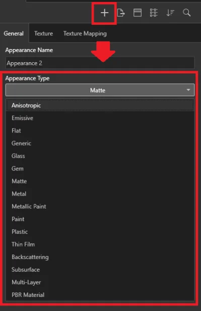
- Pick any Appearance Type that you desire. As you can see above, I chose a Matte appearance, because I wanted to make my binder clip unique. You can also choose a color as well, by selecting a color in the ‘Color’ box.
- Once you have chosen your custom appearance, you can drag your new appearance into the graphics area. I chose to make a Matte red Appearance and I dragged the appearance into the graphics area onto one of the arms of the binder clip, as seen below:
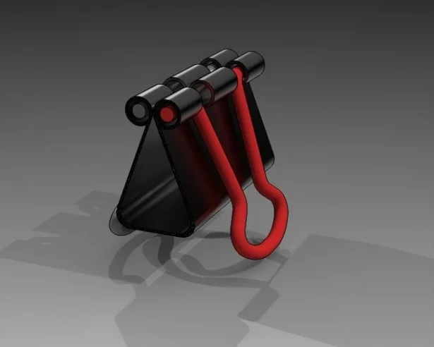
Observe here that you may interchange the appearances by just dropping a new appearance onto the model.
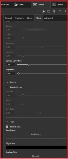
- As an added bonus for this post: a little trick I performed for this render was adjusting one of the camera options to create a “cartoon-like” effect.
Navigate to the ‘Cameras’ tab and then the ‘Filters’ sub-tab. From here, scroll down to ‘Toon’ and select ‘Enable Toon.’ You may use a ‘Toon preset,’ but can also start with one and change the ‘Edge Color’ and ‘Shading Style’ to create a custom Toon appearance:
4. Why does the last used ‘BOM template’ not remembered while inserting a new BOM, instead it always uses ‘standard BOM’ Template?
– By Daniela KOLOSZKO
Until SOLIDWORKS® 2021, the most recent used ‘BOM template’ was remembered, and suggested as the one to use when creating a new BOM, often meaning a customer’s custom BOM template was used each time.
Starting from SOLIDWORKS® 2022, you would have observed that each time when you create new BOM, the ‘bom-standard’ template is suggested as the one to use, and the most recent used BOM is not remembered. This is an intended regression from the previous version.
However, in some specific cases SOLIDWORKS® users would still prefer to have the most recent used BOM, while creating a new BOM. Here is a suggested workflow to achieve the same:
To remember last used BOM template you have to save the ‘custom template’ in a folder and add this template folder to ‘File locations’ in System Options.
Follow the below mentioned steps:
- Insert BOM in assembly > Right click on the BOM > save as ‘bom-standard.sldbomtbt’ in folder ‘Template1’Note : The name of saved template should be same as standard template, hence save it as ‘bom-standard.sldbomtbt’
- Go to Tools>System Options > File locations > In ‘Show folders for’ > select ‘BOM templates’ > folders > add folder ‘Template1’ > move ‘Template1’ folder to top