

Hello to all,
Welcome to the new edition of the SOLIDWORKS® Support Monthly News! This monthly news blog is co-authored by members of the SOLIDWORKS® Technical Support teams worldwide. Here is the list of topics covered in this month Blog.
- Manage your DraftSight® licenses effectively using License authorization rules in DS License Server (DSLS)
- Use the SOLIDWORKS® Simulation Interaction Viewer to see bonding locations.
- Pack and Go functionality in DraftSight®
- How to use nested If-else statement in SOLIDWORKS® ?
Manage your DraftSight® licenses effectively using License authorization rules in DS License Server (DSLS)
By Gayatri KESKAR
When working with DS License Server there are times when just installing and enrolling the license file isn’t enough. For the bigger companies with multiple license for different products it’s important to manage the licenses so that certain group of users is allowed to use certain products or reserve specific number of licenses to a group so that others cannot use it.
For DraftSight® we have different packages available like Enterprise, Enterprise Plus. Let’s say there are some users who are working on a project that needs access 3D features from Enterprise Plus package. If these licenses are already occupied by user who can work with Enterprise Package, it can cause unnecessary delays and downtime for the users. To avoid this we can use authorization rules and reserve 3D license for specific set of users so that these licenses will be available when users need them.
Define users or groups to define authorization rules:
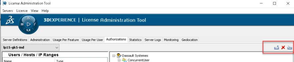
- Launch DSLS License Administration Tool
- On Server definitions tab check server is connected
- Go to Authorizations tab, Right click in a blank space under UsersHostIPRanges and select Add.
- Add UsersHostsGroups
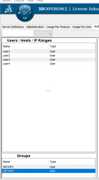
As you can see in above image we have defined 4 users and 2 groups. We will assign the group of users to access the certain licenses only. (You can see users added in certain group by double clicking on it)
NOTE: Usernames are the windows login username and hostnames are system names.
Add authorization rules:
To add the rule, go to Authorizations tab >right click on the license you intend to add a rule to and select Add new rule.
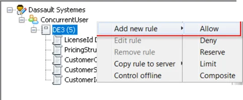
Select Allow/Deny/Reserve/Limit/Composite. We will use Reserve to reserve Enterprise Plus licenses to users (user1, user2) in this group so that other users will not be able to get these 2 Enterprise Plus licenses.
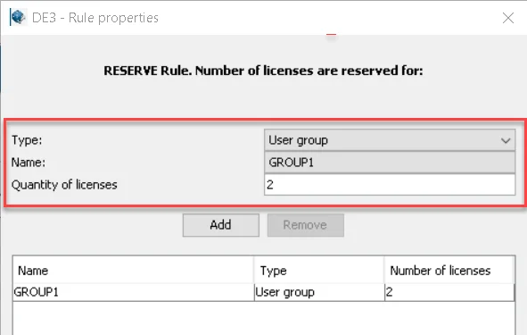
Similarly we can apply different rules to different licenses and manage how the licenses will be used. We can also export the authorization file as .xml> edit it and re-import it.
For more information about different rules refer to ‘Setting License Authorization Rules’ section in DS License Server Installation Guide.
Use the SOLIDWORKS® Simulation Interaction Viewer to see bonding locations
By Jay SEAGLAR
The Interaction Viewer is an extremely useful (and some would say greatly underutilized) tool that lets you see the exact mesh elements which will participate in solver-generated bonds.
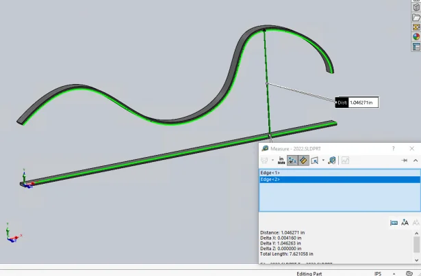
Consider the example model shown below, where the distance between the two bodies varies. The bodies are approximately 0.3 inches apart at their closest and just over 1 inch apart at their furthest:
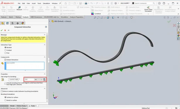
For this example, we define a Gap range for bonding value of 0.5 inches for a Global Bonded Interaction. The leftmost face of the upper body is fixed. The bottom body has a prescribed displacement of 0.2 inches down, so we expect it to “pull” the upper body down with it due to the bonding we defined.
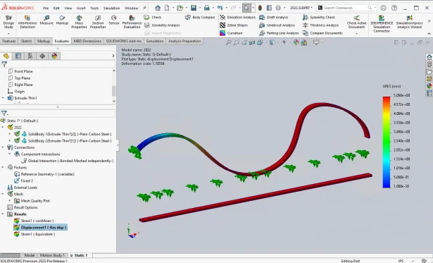
After running the study, we can look at displacement results and see that the bodies did what we expected:
However, we might also want to know which regions of the bodies were actually bonded through the Global Bonded Interaction. And perhaps more importantly, which regions did not participate in bonding.
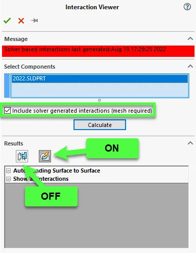
The Interaction Viewer will show you. Here is how:
- Turn on the Include solver generated interactions (mesh required) option.
- Click Calculate.
- IMPORTANT: Hide Geometry Based Interactions by turning OFF the toggle button on the left.
- Be sure that Solver Based Interactions are shown (turn ON the toggle button on the right if needed).
Now you can clearly see where the software applied bonds between the two bodies, and make adjustments to your study setup as needed:
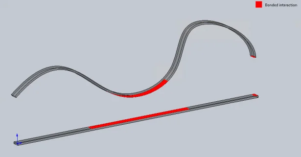
PS: The most attentive among you may have noticed the bond region all the way to the right. Those faces 0.49 inches apart, so they are just within our 0.5 inch threshold for bonding!
Pack and Go functionality in DraftSight®
By Nav MAHAJAN
With DraftSight® 2022, now you can use the PackAndGo command to create a package containing the current drawing and its dependent files such as References, referenced images, referenced PDF files, font files, font mapping files, PrintStyle files, and Print Configuration files.
You can create a ZIP file or a folder to bundle the drawing together with its related files.
Using the tabs of the Pack and Go dialog box, you can specify the files to add to the package. Optionally, you can display a summary of the package content.
To create a package containing a drawing and its dependent files:
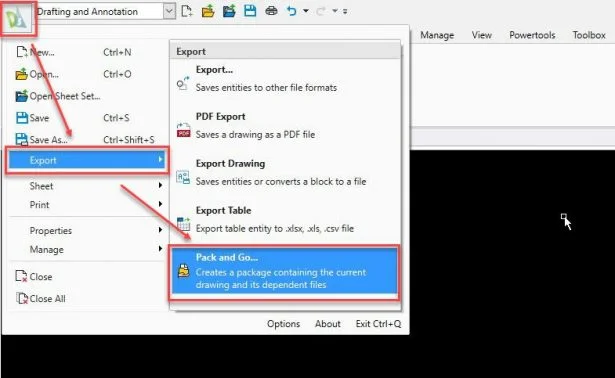
- Click File > Export > Pack and Go (or type PackAndGo).
- In the Pack and Go dialog box, specify a view mode for the package file list:
- Tree View: Displays a hierarchical list of the package files, grouped by file type.
- Table View: Displays the included files a table format with file name, path, type, DWG file version, size, and date columns.
Select the check boxes in front of the file names to specify whether the file is included or excluded from the package. By default, all dependent files are included.
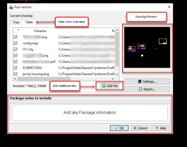
- Click Add File to add additional files to the package. Use this option if you want to include other external files related to the drawing (but not directly referenced in it), such as customization files, text documents or spreadsheets.
- Click Settings to set preferences for the packaging.
- Set options in the Pack and Go Settings dialog box.
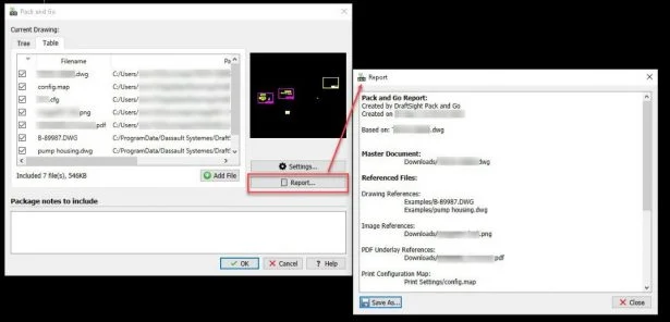
- Click View Report to view a summary of the package contents. The Report dialog box shows detailed information about the package contents and provides distribution recommendations. The report may be written to a text file.
- For Package notes to include, you can type notes to include in the package (for example, project status information).
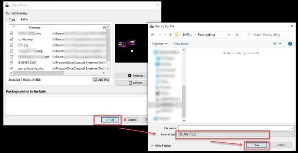
- Click OK.
- Type the file name for the ZIP file and click Save.
Setting Preferences for Packaging Drawings You can create a ZIP file or a folder to bundle the drawing together with its related files. Using the options available in the Pack and Go Settings dialog box, you can:
- Create a ZIP archive file or gather the files in a specified folder.
- Specify how to organize the files and folders in the package.
- Discard all unused references from the drawing you pack.
To set preferences for packaging drawings:
-
- In the Pack and Go dialog box, click Settings to set preferences for the packaging.
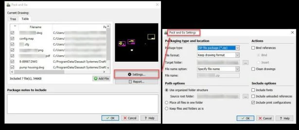
- In the Pack and Go Settings dialog box, under Packaging type and location, specify:
- Package type: Creates a ZIP archive file or gathers the files in the specified folder.
- File format: Specifies the existing drawing file format or saves to an earlier version.
- Target folder: Specifies the output folder for the package.
- File name option: Specifies what to do if a ZIP file with the same name already exists in the output folder (prompt for a file name, overwrite file, or increment file name).
- File name: Displays the ZIP file name (same as the master drawing name).
- In the Pack and Go dialog box, click Settings to set preferences for the packaging.
Under Path options, specify how the files and folders are organized in the package (ZIP files or folders):
-
-
- Use organized folder structure: Creates a hierarchical folder structure based on the file structure. Click Browse to specify the root folder of the source.
- Place all files in one folder: Use this option if you are unsure whether the package recipient has a folder structure similar to yours.
- Keep files and folders as is: Recreates the exact paths of the existing files.
-
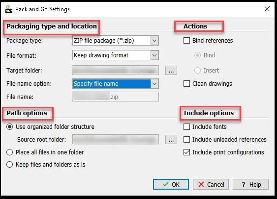
Under Actions, specify actions performed before packaging the drawing:
-
-
- Bind References: Makes referenced drawings a permanent part of the master drawing. The option transforms referenced drawings to Blocks in the master drawing and incorporates dependent symbols such as Layers, LineStyle definitions, TextStyles, and DimensionStyles into the drawing. The option functions as if you use the -References command with the Bind option before packaging.
- Clean drawings: Discards all unused references from the drawing you pack. The option functions as if you use the Clean command before packaging.
-
Under Include options, specify:
-
-
- Include fonts: Includes or excludes fonts used in the drawing in the package or from the package.
- Include unloaded References: Specifies whether links to reference files are maintained, although they are unloaded and no longer visible in the drawing. The Reference palette lets you unload and reload file references.
-
Click OK. In the Pack and Go dialog box, click OK to start packaging.
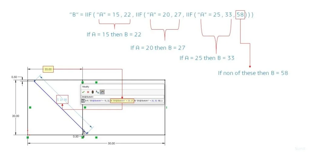
How to use nested If-else statement in SOLIDWORKS® ?
By Sumit RANA
Noteworthy Solutions from the SOLIDWORKS Knowledge Base

When I use the SOLIDWORKS® PDM quick search or integrated search functionality, why do the SOLIDWORKS file open or save dialog boxes stop responding (hangs or crashes)?This problem can happen on a SOLIDWORKS® PDM client workstation if the file type associations for SOLIDWORKS files are incorrect. To get more information, see solution ID: S-079778

What can I do if every SOLIDWORKS® Flow Simulation project I run shows a ‘Preparing model’ Solver Monitor status indefinitely and any FloXpress analysis never finishes the ‘Meshing in progress’ step?To get more information, see solution ID: S-079776
When I open the SOLIDWORKS® Manage web interface, why do I see the message ‘There is no dashboard to display’ ? After you configure a SOLIDWORKS® Manage incident on the server and then open the incident with the web, when you select the dashboard sometimes this message appears. To get more information, see Solution ID: S-079652