

Hello to all,
Welcome to the new edition of the SOLIDWORKS® Support Monthly News! This monthly news blog is co-authored by members of the SOLIDWORKS® Technical Support teams worldwide. Here is the list of topics covered in this month’s Blog :
-
Utilizing External References for Dynamic Suspension System Representation
-
SOLIDWORKS® Toolbox: Some quick tips
-
Visualize Connected – How ‘Live-Update’ works when ‘Monitor File’ option is not available for CAD model opened from 3DExperience
1. Utilizing External References for Dynamic Suspension System Representation
-Kundlik GADADE
Creating an animation for a suspension system involves intricate dependencies and precise assembly. In this example, we’ll delve into the process of animating a Double Wishbone Suspension System, commonly found in high-performance vehicles like Formula Cars, utilizing external references for dynamic motion.
1. Model Components Individually: Begin by modeling each component separately: the Spring, Damper, Bell Crank, Push Rod, and A-arm (Upper A-Arm). Notably, the Spring is created using the Sweep command. Here’s a step-by-step guide:
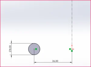
- Defining Spring Profile:
- Start by drawing a circle to define the coil profile.
- Constrain the profile’s location to specify parameters such as wire diameter and coil outside diameter.
- Path Definition:
- Define the path for the sweep, typically aligned with the spring’s free length.
- Ensure one end of the path remains unconstrained in the sketch, allowing for path length adjustments.
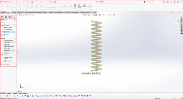
- Sweep Creation:
- Navigate to Features > Swept Boss/Base.
- Select the sketch for both Profile and Path under Profile and Path options.
- Configure sweep options accordingly.
- Confirm by clicking Ok.
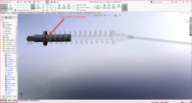
2. Assembling Components with External References: Assemble the components, ensuring proper mates to facilitate desired motion. Notably, the spring is placed around the damper, necessitating external references. Here’s how:
- Creating References:
- Identify points of reference, such as the concentricity between the damper cylinder and the spring.
- Enter the part’s Edit Part mode.
- Access the spring’s Path sketch and establish a coincident constraint between the unconstrained endpoint and the designated point on the Damper Piston.
3. Animating the Assembly: Animate the assembly to visualize its dynamic behavior using the following steps:
- Setting Up Motion Study:
- Access the Motion Study tab.
- Adjust the time bar to determine the animation duration.
- Animating the Components:
- Drag the components to their desired end positions.
- Calculate and play the animation to observe the system’s motion.
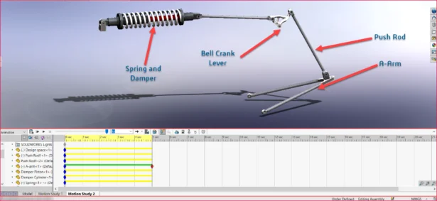
Leveraging External References for Dynamic Animation: External references play a crucial role in accurately depicting the compression of the spring and the overall motion of the suspension system in this example. By calculating each frame with respect to these references, the animation realistically portrays the system’s behavior.
Conclusion: Animating a suspension system with external references adds depth and realism to the animation. By meticulously modeling and assembling components, and leveraging external references, you can create dynamic animations that effectively illustrate the system’s functionality.
Below showcases the end result of the animation:

2. SOLIDWORKS® Toolbox: Some quick tips
– by Gaurav GAYAKWAD
Often while editing the Toolbox components we run into and unknown error and we wonder what could be the possible cause of it. In the below points I tried to address few of the commonly misunderstood points while editing Toolbox components.
1. Why I am not able to add any additional configuration to the table using the export and import option?
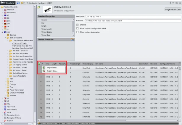
When you’re handling exported data in Microsoft Excel®, you only have the option to input Part Numbers, Descriptions, and Comments which are the user input fields.
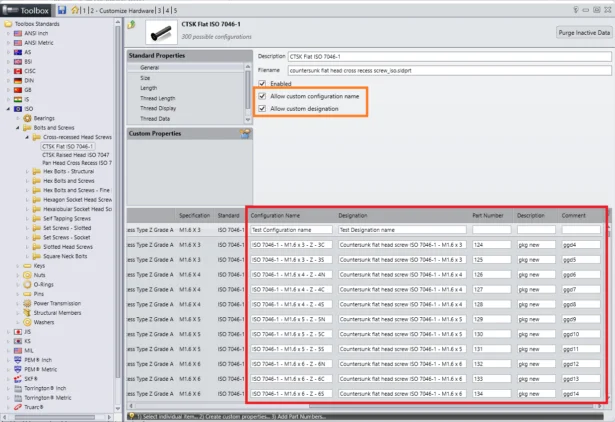
You can even customize configuration names and designations within the designated columns but only when ‘Allow Custom Configuration name’ and ‘Allow custom designation’ is checked. Meaning these columns are also opened for user input data.
But it’s important to note that user must refrain from adding or modifying any other information within the spreadsheet.
Even though you can see properties like Size, Length, Recess Type etc. definitions for Toolbox components in the table, you should not specify or change the value definitions in the spreadsheet.
Any alterations made to data in columns outside of these specifications will result in the spreadsheet failing to import correctly into the Toolbox Settings.
Most common mis-understanding related to this option is we can add new size and all the configurations in the excel table and import it directly in the Toolbox which is not true. The import and export of excel is for the text editable fields like Configuration Name, Designation, Part Numbers, Descriptions, and Comments.
You can only add new size from the Toolbox > Standard Properties > Size.
2. What is the use of ‘Create Configuration / Parts’ option?

This is one of the most under rated option which can be very helpful if the CAD Admin who setup the Toolbox initially in the company, know the correct use of this option.
The ‘Create Configuration / Parts’ option reduces the time needed to create a new configuration or part while using the Toolbox.
Whenever a user adds any component in the assembly for the first time a configuration or part (depending upon the settings in 3-User Settings page) is created in master part file or parts in a specified folder. Now doing this for a single component takes very less time but this time can also save if we create all the configurations or parts in advance at once.
3. Should I open the parent part or the created part and change the sketch or dimensions of part as per my requirement and continue to use it as Toolbox part.
It’s not advised to change the Toolbox parent part or the derived part directly by opening the part. You are most likely to run into an error due to an unsolved equations resulting in error in sketches.
You should change the Toolbox components from the Toolbox Settings page only, this not only will guides you to only edit the editable parameters but also will avoid any errors.
4. What is the use of ‘ToolboxStandards.xml’ file in the Toolbox folder?
This file is created during the installation of SOLIDWORKS. The Installation Manager lets you specify which Toolbox standards to install, making it easier to manage the Toolbox data.
You are able to turn-on (<Install>Yes</Install>) and turn-off (<Install>No</Install>) standards from this file. The ToolboxStandards.xml file stores the choices made in this process.
Standards marked as “No” will be ignored during the upgrade process. Reviewing this file can be useful for determining why a standard is missing or hasn’t been updated.
3. Visualize Connected – How ‘Live-Update’ works when ‘Monitor File’ option is not available for CAD model opened from 3DExperience
– by Vinod KALE
Visualize has a useful setting Monitor File that allows a Visualize project to update any changes made to the imported CAD model from SOLIDWORKS. There are two ways to activate it:
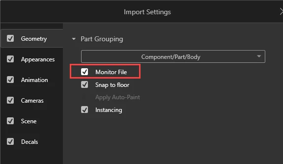
- When you import a CAD model from local drive, you can select the Monitor File option in the Import Settings dialog as shown below
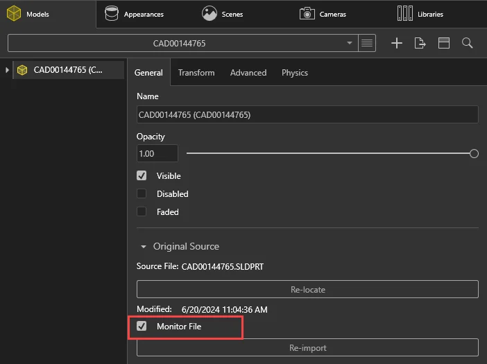
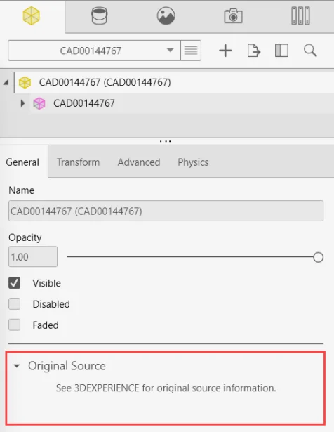
- The other way to enable or disable the Monitor File option is after you have imported the model in Visualize. Navigate to Palette, select Models tab and expand section ‘Original Source to toggle this option.
However, the Monitor File option is not available when you import a CAD model from 3DEXPERIENCE platform in Visualize Connected. It says ‘See 3DEXPERIENCE for original source information’ as shown below.
The ‘Monitor File’ option has been excluded from Visualize Connected for data imported from 3DSpace, as per the compatible design specification for this app.
For a dependent file opened from 3DEXPERIENCE, the reference is not based on a file path, but on a Physical Product ID instead. A FileWatcher is not used in this case. Live update is triggered when a user selects open and/or changes revision on a dependent file via the MySession. Since there is no file monitoring when importing data from 3DEXPERIENCE, the Monitor File checkbox is excluded from the import dialog.
For a CAD file imported from local disk, it remains unchanged Monitor File option is available in ‘Import Settings’ dialog, and file watching mechanism is used to trigger ‘Live Update’.
How ‘Live Update’ project works in Visualize Connected?
- Open the CAD specific data or project in Visualize Connected
- Open the same CAD file from platform in SOLIDWORKS Connected
- Make some changes and save to platform.
- In Visualize Connected, notice the status under MySession shows orange color arrow
- Hover the cursor on that arrows, it shows ‘A more recent version of the file exists in 3DEXPERIENCE’
- Right-click on the part and select ‘Reload from server’. It displays warning ‘The data in 3DEXPERIENCE has changed and you are no longer working on the latest version’
- Click ‘Yes’ to update the data to latest version. Observer the changes made in CAD file in SOLIDWORKS Connected are updated here
- In MySession, right-click the project, select Lock and then save to platform.