

Hello to all,
Welcome to the new edition of the SOLIDWORKS® Support Monthly News! This monthly news blog is co-authored by members of the SOLIDWORKS® Technical Support teams worldwide. Here is the list of topics covered in this month’s Blog :
-
Use of routing library components from 3DEXPERIENCE platform by multiple users
-
How to add watermark on the Drawing Sheet? Approach -2
-
When updating a file for 3DEXPERIENCE compatibility, Design Table reverts custom value assigned to ‘$PartNumber’ to ‘$C’ when opened. Why?
-
Understanding the calculations of Costing
1. Use of routing library components from 3DEXPERIENCE platform by multiple users
-by Vinod KALE
In general, when you work with SOLIDWORKS Routing, the routing library is accessed from the below default routing library location. <C:ProgramDataSolidWorksSOLIDWORKS <version>design libraryrouting>
In order to access these routing components from platform by multiple users:
A. Upload all library parts and assemblies to 3DEXPERIENCE platform by one User on that machine.
- Launch SOLIDWORKS Connected or Design with SOLIDWORKS
- Go to Tools, select Options and click Routing
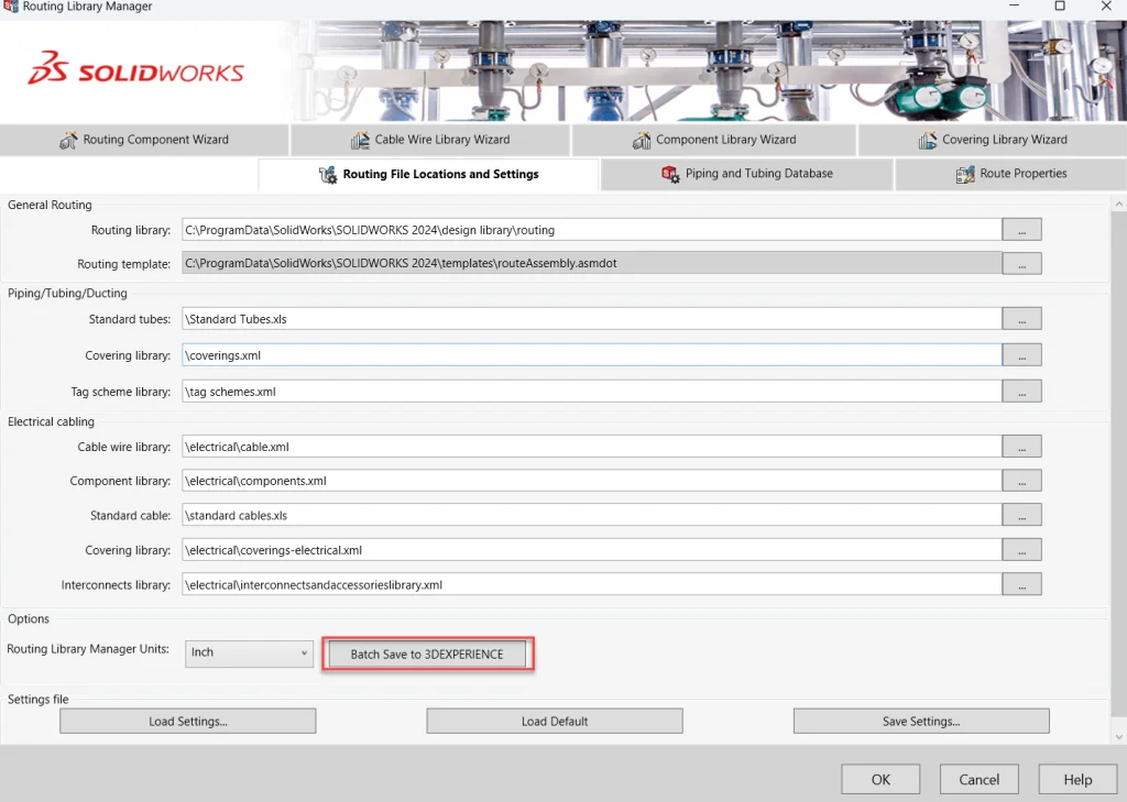
- Select Routing File Location and launch Routing Library Manager (RLM)
- It goes to Routing File Locations and Settings tab by default
- Click Batch Save to 3DEXPERIENCE; select the required Collaborative Space and Save the data to platform
- In RLM, click Save Settings to save all routing settings
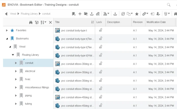
- Navigate to Bookmark Editor on platform and share the bookmark with another user.
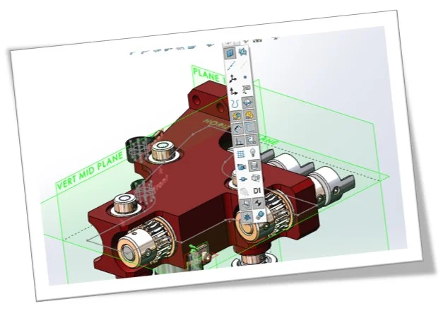
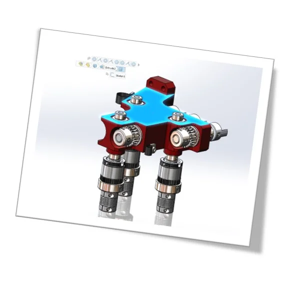
Batch Save to 3DEXPERIENCE currently uploads only the SOLIDWORKS files as CAD Family and Physical Product on the platform as shown in below image.
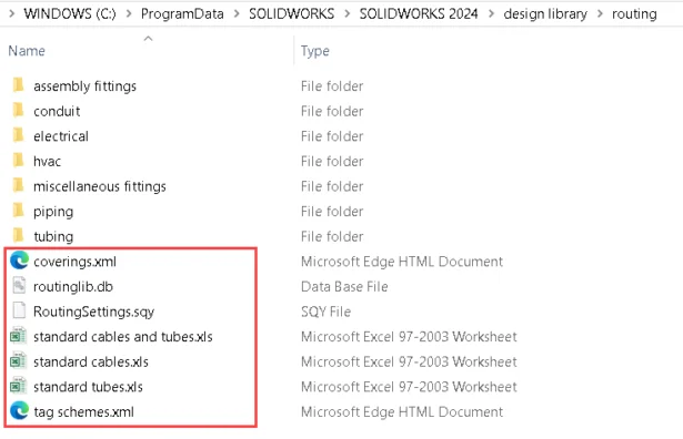
Non-SOLIDWORKS files like routinglib.db, coverings.xml, etc. shown in below image from routing library cannot be uploaded using Batch upload process. You need to ‘Drag and Drop’ these files from windows explorer to platform under Bookmark.
B. Access the routing library components from platform by another user from different machine.
- Logon to 3DEXPERIENCE with another user login
- Launch SOLIDWORKS Connected or Design with SOLIDWORKS
- In order to use the routing library components from platform, the user first need to download it on the local drive
- For that, open Routing Library Manager and set the default routing library folder path to Bookmark (where routing data is saved).
- The default library folder path in RLM then changes as shown in below image <C:UsersPublicDocumentsSOLIDWORKSTenant-IDAlpha-Numeric Number>
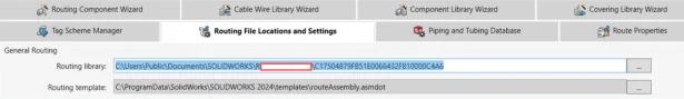
- Save all routing settings
- Whenever this user launch SOLIDWORKS and use the routing library components on this machine, it is accessed from the location mentioned in step-5.
2. How to add watermark on the Drawing Sheet? Approach -2
-by Tushar NAYAK
In last month, we learnt a technique to add watermark on the Drawing Sheet using Approach-1 i.e. using ‘behind the Sheet’ Notes. In this one, we will see another approach of adding the watermark. You may also add a watermark using a Word document as an Object. This Object can be a picture, Microsoft PowerPoint Slide, A Word document etc.
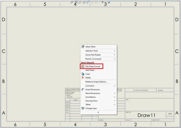
To add an Object as a watermark on the sheet, start by creating a new drawing with required sheet size and format. Right click on the blank area of the sheet > Edit Sheet Format.
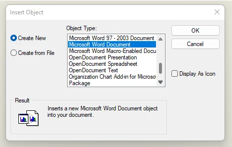
Then go to Insert > Object > Create new. The ‘Object Type’ section shows various objects that you can insert onto the drawing sheet. Scroll down in the list > Select ‘Microsoft Word Document’ > OK.
This replaces SOLIDWORKS Command Manager with the commands of Microsoft Word. Go to Design tab > Watermark > Custom Watermark > text Watermark. In Printed Watermark window, set required Text, Font, Size, Color for the Watermark text.
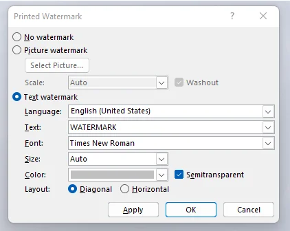
You may here choose to keep Watermark diagonally or horizontally and make it semi-transparent. Once all these are set, click Apply > OK. The watermark appears in SOLIDWORKS but is not correctly positioned. Drag it to correct position and click outside the sheet to apply the Watermark. Currently this Watermark appears in front of the views, title block, however, it is supposed to appear at the very back of the sheet content. Right click on the object, select ‘Send to back’.
Right click in the blank sheet area, click on ‘Edit Sheet’.
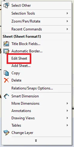
There you are! You may now save this as Drawing Template for future use.
3. When updating a file for 3DEXPERIENCE compatibility, Design Table reverts custom value assigned to ‘$PartNumber’ to ‘$C’ when opened. Why?
–by Ankit GUPTA
SOLIDWORKS Desktop users transitioning to 3DEXPERIENCE SOLIDWORKS might encounter a peculiar issue where the assigned part numbers revert to “$C” upon opening. This blog aims to shed light on this phenomenon and propose practical solutions to mitigate it.
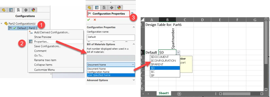
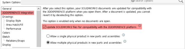
When the 3DEXPERIENCE integration option is disabled, the $PARTNUMBER parameter in a design table allows you to specify a different value (Custom Part no.) for the ‘PART NO.’ column of the BOM. The same can be achieved through configuration properties for ‘Bill of Materials Options’.
Please refer to the help document for more details: https://help.solidworks.com/2024/English/SWConnected/swdotworks/r_Component_Part_Number.htm?id=16c5ed5ed38b48638fa043f44926564b#Pg
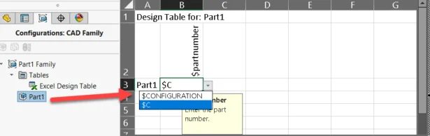
After the part is updated to 3DEXPERIENCE Compatibility, the PartNumber is driven by the Physical product name (configuration name). Therefore, any manual entries in the Design table for $PartNumber column are overridden and change to $C, representing the Configuration name.
Proposed Solutions:
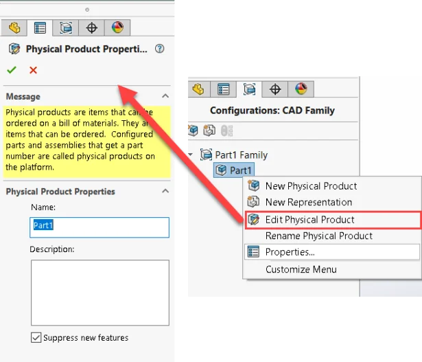
1). Setting Physical Product (Configurations: CAD Family) Name: By aligning the Physical product name with the desired part number, users can ensure consistency across their designs.
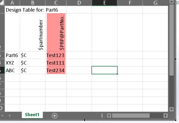
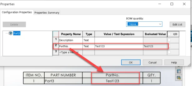
2). Another option is to add a configuration-specific property, such as ‘PartNo,’ for the Physical Product. This involves adding a column for this configuration-specific property in the Design table ($PRP@PartNo) and then including a ‘PartNo’ column in the BOM table in the drawing.
4. Understanding the calculations of Costing
–by Gaurav GAYAKWAD
Many a time user get a final cost of a machined part and is not sure how the calculations for each sections got calculated. In this blog we will try to understand calculations behind each value in the Costing with the help of an example.
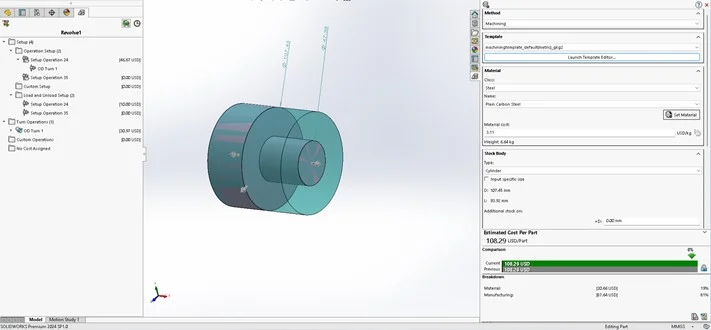
In this example we are going to calculate costing for a simple turning part which has only two steps (image shown below). In this the small diameter is 47.38mm and bigger diameter is 107.45 and the length from front face till back face is 50.09mm.
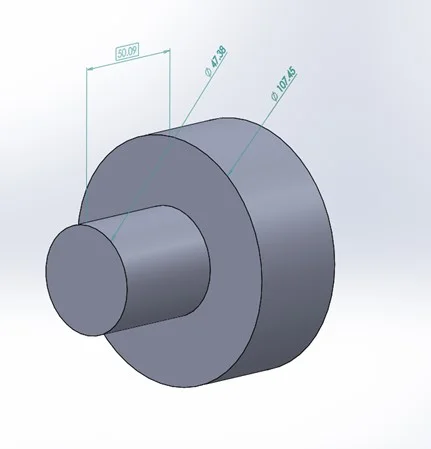
We have only taken into account the stock relevant to turning operations.
When we do the costing of this part, we get a total cost of 108.29 USD/Part.
The two major components are ‘Manufacturing’ and ‘Material’ cost. The SOLIDWORKS Costing tool has determined the manufacturing cost to be 87.64 USD and the material cost to be 20.66 USD, as depicted in the image below.
MANUFACTURING COST
In our example, manufacturing cost consists of following 3 components
- Operation Setup = 46.67USD
- Load and Unload Setup = 10.00 USD
- Turn Operation (OD Turning) = 30.97 USD
Let’s understand the calculations of Operation Setup.
1. OPERATION SETUP: 46.67 USD
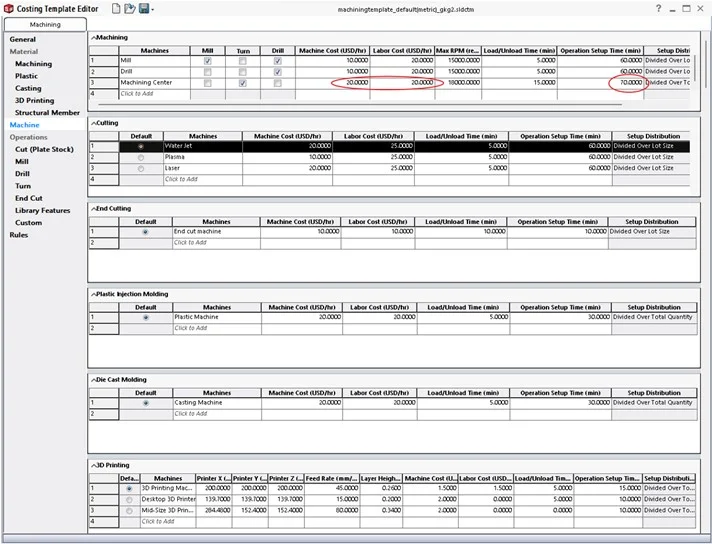
This is the setup cost and this cost is derived from ‘Operation Setup Time (min)’ in the ‘Machine’ tab of Costing Template.
Calculations:
- Formula: Operation Setup Time * (Machine Cost + Labor Cost)
- Converting ‘Operation Setup Time’ of 70 minutes to hours, will be 1.16hrs.
- From the above image ‘Machine Cost’ is 20 USD/hr and ‘Labor Cost’ is 20 USD/hr.
- Total cost for loading and unloading is 1.16 * (20+20)= 40 USD.
Logic: While parts were being setup, the machine remained operational and labor was occupied hence machine and labor cost both are applied.
2. LOAD AND UNLOAD SETUP COST: 10.00 USD
This cost is Load and Unload cost. This is derived from ‘Load/Unload Time (min)’ in the ‘Machine’ tab of Costing Template.
Calculations:
- Formula: Load/Unload Time * (Machine Cost + Labor Cost)
- Converting ‘Load/Unload Time’ of 15 minutes to hours, will be 0.25hrs.
- From the above image ‘Machine Cost’ is 20 USD/hr and ‘Labor Cost’ is 20 USD/hr.
- Total cost for loading and unloading is 0.25 * (20+20) =10 USD.
Logic: While parts were being loaded and unloaded, the machine remained operational and labor was occupied hence machine and labor cost both are applied.
3. OD Turning: 30.97 USD
This is the actual machining cost for OD turning operation. This cost is derived from the calculation based on ‘Turn’ page of ‘Operations’ section in Costing Template.
The first thing you will observe is that there are few filters applied in above image. Let’s try to understand them.
- Class: Steel; This is the class of material we will chose to machine.
- Custom Material: Plain Carbon Steel; This is the custom material (alloy) that will be machined.
- Machine: Machining Centre; This is the machine on which the operation is being done.
- Tool Type: OD Turning; This is the operation for which the parameters are defined.
- Surface Furnish: Roughing; What kind of operation is being considered for machining.
- Rest columns have values of different machining parameters.
Logic: To calculate the cost of machining. We must know at what rate the machine removes volume for a specific operation.
In our example we must know at what rate machine ‘Machining Centre’ will remove volume while doing OD Turning operation.
This rate is calculated by calculating Material Removal Rate (m^3/min). The formula is as given in above image. MRR=(S*Fr/1000*d/1000)
Calculations:
- Calculating MRR with the defined values = 0.000007875 m3/min
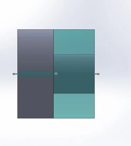
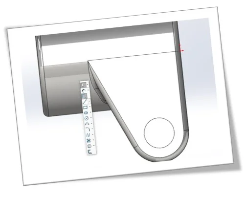
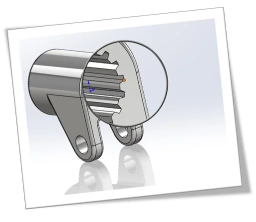
- Now calculate the volume to be removed. Se below picture.
We can calculate this volume by calculating volume of big cylinder and then subtract volume to small cylinder. The length for both is 50.09 mm. After final calculation the volume to be removed comes out to be 0.000365807m3.
- Now to calculate final time. It will be time required to remove 0.000365807m3 with 0.000007875 m3/min MRR. It will be 0.000365807/0.000007875 min, which is 46.45 minutes.
- Formula: Time required to remove material * (Machine Cost + Labor Cost).
- From the above image Machine Cost is 20 USD/hr and Labor Cost is 20 USD/hr.
- OD machining (Roughing) = 46.45 minutes * (20 USD/hr + 20 USD/hr) = 0.77416667 hrs * 40USD/hr = 30.97 USD
TOTAL MANUFACTURING COST is OPERATION SETUP COST + LOAD AND UNLOAD SETUP COST + MACHINING COST (OD TURNING)
CALCULATIONS = 46.62 USD+10 USD+30.97 USD = 87.59 USD
MATERIAL COST
The material cost is the cost defined by user on Machining page of Material section for a specific material class and stock type.
In our example we have ‘Steel’ material, ‘Plain Carbon steel’ alloy, and stock type is ‘Cylinder’.
The cost defined is 3.11 USD/kg (see image below).
The weight of material is as shown on image is 6.64 kg. So, the cost of material comes out to be:
CALCULATIONS = 3.11 * 6.64 = 20.64 USD
TOTAL COST:
= MATERIAL COST + MANUFACTURING COST
= 87.59 + 20.64 = 108.23 USD