
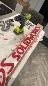
Anyone who knows me will know I spend a large portion of my workday with SOLIDWORKS open on one screen and a video meeting on the other. Recently I’ve been thinking of ways I could make my webcam background look a bit more SOLIDWORKS-orientated. After scribbling out some rough ideas (and crossing out some rather quickly) I decided I wanted to put the SOLIDWORKS logo on the wall behind me.
My first sign-making idea involved making each letter individually and drilling a vast number of holes into my wall to secure them separately. However, my head told me this wasn’t the most efficient or neat way to complete the project. After some more sketches and some additional thoughts, I decided the best way forward was to design an assembly containing each letter of the logo being mounted to one piece of acrylic matching the shape of the outline.
The first stage of this project would be finding the SOLIDWORKS logo in a decent resolution to use as the base for my design. With this image in hand, I used a piece of software to turn the logo into a SVG vector file before importing it into 3DEXPERIENCE SOLIDWORKS for Makers. For anyone who doesn’t know, 3DEXPERIENCE SOLIDWORKS is basically 99% of premium SOLIDWORKS available to makers and hobbyists for an affordable monthly or yearly cost. If you haven’t already, it’s worth checking out.

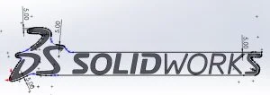
After importing the SVG file into 3DEXPERIENCE SOLIDWORKS I simply used this created sketch to create a new 3D body. Before I could conduct the simple extrude command, I needed to check the size of the imported geometry. Upon measuring I found this to be way to big for the wall space I had on offer. Luckily, SOLIDWORKS has a Scale command which can be applied to sketches! I use the Scale command to reduce the size of the sketch to the required 850mm width. Once I was happy with the size of the sketched lettering I used the Extrude command to extrude 10mm.

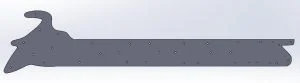
With the basic lettering now made into a useable 3D shape my next challenge would be to create the outline of the backing board onto which I would mount all the letters. To do this, I created a new sketch on the back surface of the lettering. Onto this I offset the circumferential edge of the “DS” lettering along with the last “S” on “SOLIDWORKS”. This offset edge would form the edge of the backing board. To join these offset sketches together, I added some lines above and below the text with a gap equal to that of the offset. From this point it was easy sailing, adding some splines in to join up all the loose lines. Once these were all together it was a simple task of using the Power Trim command to remove any lines which were no longer needed.
With this sketch created I chose to extrude this created sketch shape the 5mm distance equal to that of the thickness of the material I would be using: in this case I had chosen clear acrylic to really make the letters stand out from the wall. Once this was done, I needed to think about how the letters would be held in place. I decided I would use some threaded fixings from behind to achieve this. To create the required through holes in the backing board I used the lettering in the assembly to create a new sketch and position some 4mm diameter holes within their outline. Once I had all of these in the correct position, I use the Extrude Cut command to remove the needed material by selecting through all. Once this was completed, I created a sketch on the rear sign surface before converting all edges into lines using the Convert Entities tool. This sketch was then used in another part to create the backing board on its own. The final step was to save the DXF used for the laser cutting process.
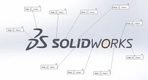
With the backing board complete it was time to add the mounting holes to the lettering. Luckily because I’d used the sketch originally to locate the hole on the board, I could change the feature settings to extrude these from the back surface of the lettering 5mm deep. I didn’t want these holes to penetrate through the letters as I wanted to keep a clean looking front face to the sign. From here it was pretty simple. I used the Save Bodies command to select all bodies before renaming each to an appropriate title and saving.
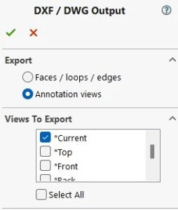
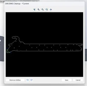
With the majority of the SOLIDWORKS modeling complete it was time to get everything prepped for manufacturing. As mentioned earlier the backing board was going to be laser cut from 5mm clear acrylic material. With any laser cutter, the easiest file to work with is a 1:1 sized DXF. I opened the part file for this, orientated it to the correct position before using the file type drop down in the save as menu to select DXF. Upon clicking save, a menu pops up asking you to select a view, I always select current and ensure I’ve positioned the part accordingly beforehand. It would be easy enough with this part to select the correct plane option but with a more complex it can sometimes become trickier to keep tabs on what’s where. For the letters I would be 3D printing a master pattern before creating a silicone mold to create resin casts. If I was only making one of these signs, I’d have probably just accepted a 3D print for the letters but as I’d had a few people asking for one I thought it would be easier to future proof in case I needed to make any more down the line! To do this I saved each letter as an STL file using the same option menu as where DXF was selected from previously.
The making for this one involved a bit of subcontract work up front. My in-house laser cutter can only cut widths up to 400mm, and whilst I could have split the backboard and used some dovetail type joints to lock 2 pieces together, this would have affected the clean look I was going for. Luckily, I have a local contact who runs a shop specializing in industrial size laser cutting who was able to lend a hand. I sent the files off and a week or so later had parts in hand to work from. As for the letters, again, I have in-house capability to 3D print them, but I wanted to save on the sanding process needed to get a good casting surface. Luckily, there’s a load of 3D Printing bureaus available online which will print in SLS Nylon for a fee. I uploaded my STL letter files, ordered and again a week later they landed in my letter box.
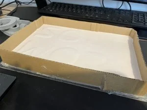
With my letters now printed it was time to get to work creating a mold. I’d originally planned to make one mold per letter, but time constraints meant I skipped this and made two large molds encompassing numerous letters in one go. Arguably I used a lot more silicone than I would have but time is valuable, and this was far quicker! As you can see below my first mix of silicone wasn’t enough to cover the letters to a deep enough depth, so I had to mix up some more and pour again. Once the two molds had set, I pulled these free from the 3D printed masters and began the casting process.
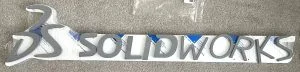
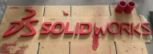
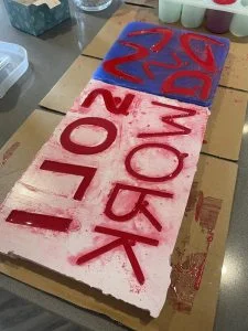
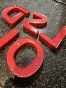
I wanted to make these letters really pop off the wall. Rather than just using a boring white resin I wanted to replicate the bright red of the SOLIDWORKS logo as best as possible. I could easily have just added some red pigment to the resin mixture to dye this red. But I wanted to do more than that as I knew a few of these would be ending up in the hands of blog readers! I elected to add a metallic red pigment to the molds before casting into the cavities to produce a bright metallic surface finish. As you can see while this method gives a great finish it does create a lot of mess on the molds. Fortunately since these are silicone nothing really sticks to them, and the coloring can easily be wiped off with some hot soapy water.
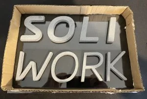
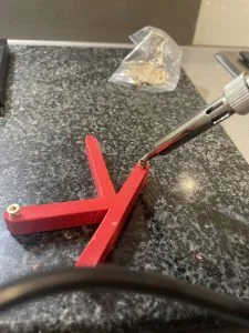
After casting it was a process of using the 3D printed letters as a jig to mark whole positions in the prints before using a hand drill to drill these out. I started by drilling through the counterbore holes and then marked through these. Once all the holes were drilled, I used some small M4 heat set inserts carefully inserted into the created holes to allow me to bolt these into positions on the acrylic backing board. For fixings I used some 10mm length M4 cap head type screws.
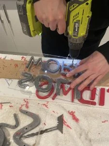
The final piece of this build was to position two extra holes into the acrylic to allow me to fit the sign to the wall, this was something that had slipped my mind during the CAD portion of the build and from previous experience I knew to start with the smallest possible drill bit when drilling these holes to prevent cracking the acrylic sheet. With these drilled I used some stainless-steel advertising standoff type fixings to secure to the wall.
I hope you enjoyed following along with my latest 3DEXPERIENCE SOLIDWORKS for Makers project and look forward to creating more cool projects soon!