

Is a dice roll really random? Let’s find out using SOLIDWORKS
If you’ve ever wondered if a dice roll is truly random, you’re not the only one. I’m adamant it isn’t and that hand rolling dice needs to be avoided at all costs. Dice towers are a great solution to get a truly random roll. With this in mind I decided to make my own.
3DEXPERIENCE SOLIDWORKS for Makers is a great offer which lets makers like me have access to SOLIDWORKS software for an affordable monthly price! It’s a great deal which you really need to check out. With this fact and my mind set on the non-random nature of a dice roll, I decided it was time to set about making my own dice tower! I jumped into 3DEXPERIENCE SOLIDWORKS for Makers and began sketching out the parts I’d need to make my tower.
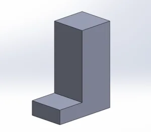
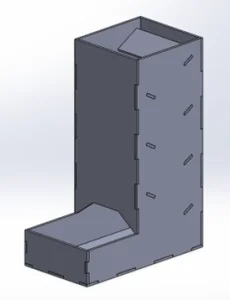
Step one of this build was to create a 3D model of the tower before sectioning it into the 2D flat pieces that would create the tower in real life. I’d be using my laser cutter to make this project. Due to my cutters size restrictions, I’d need to keep any singular part to a size smaller than 310x200mm. I set about making the 3D model by creating a simple sketch in the right plane before extruding this to my final external size. This was a very rough model which I used to get the final size and shape locked in before beginning to set about finalizing the detail of how the tower would be made.
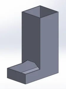
Once I had an outline shape that I was happy with, I started to use simple cut extrudes to remove material and get closer to the final vision of what the tower would look like. In what felt like no time, I had something resembling the hollow tower in which the dice could fall through and randomly roll. My next step was to split this up into the main parts which would need to be cut, I did this by creating several sketches on the model before using these to create new parts to match. I could have done this by dividing the model up into separate bodies, but I’ve always found this to be a bit messy. I saved the newly created parts before using them to create an assembly which would be easier to edit and manipulate as I continued the design process. I used some simple coincident mates to line up the created pieces correctly and saved this under a new title.
The next and arguably most difficult part of this make was to work out how I could use small tab features to lock the separate parts into position. I’ve seen this done loads of times on model kits but never had a go myself. I thought it would be best to do some small test designs which I could laser cut first to get the tolerancing on the cut right. The laser beam used to cut the material has a thickness of around 0.1mm so my first iteration was to create parts which had no overlapping sketches and see how these would fit together. It turned out that the first iteration of cuts worked pretty well, they fit snuggly together where they’d be able to be secured with a dot of super glue without issue.
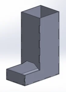
Once I was happy that I had the correct tolerance or offset value to use I started to add several areas which would allow the pieces to interlock. Again, to create this I used the most basic of features available within 3DEXPERIENCE SOLIDWORKS, extrude and cut extrude. To make this process easier, I adjusted one part at a time before updating the assembly using the traffic light in the top toolbar ribbon to ensure it was all lining up correctly. There’s a neat feature within 3D EXPERIENCE SOLIDWORKS called Tab and Slot which would do this for you but as I wanted this design to be done using basic entry level features, I took the old-fashioned approach. I think by using these simple features it allows anyone with any experience level to get involved and give making a go.
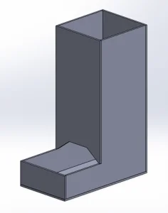
The next and final features to add were the angled paddles which would cause the dice to flip as they bounced between them. To get this effect to work I needed to create the small paddle parts. I did this by creating a simple sketch to match the width of the tower’s inner surfaces. Once I was happy with this external size I added some small tabular features to each end, which would be used to hold these paddles in place within the tower. Then I added these new parts to the assembly and positioned them as needed. Finally, I added some cutouts in the side panels to match the mating surface of the paddles.
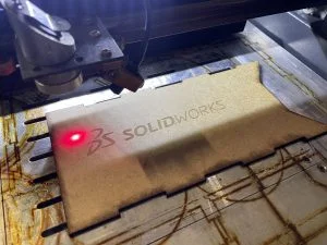
With the tower assembly now manufacturable I wanted to add some details to show that it was made using 3DEXPERIENCE SOLIDWORKS. I had two options at this point on how I could achieve this, I knew I wanted to incorporate the SOLIDWORKS logo, and I could either do this as a separate part or by etching the surface of another existing part. As I’d not played around much with engraving opposed to cutting using my laser cutter, I decided that I’d give this a go. The other option was to cut the letters as separate parts and layer this to achieve a more 3D look, but I had concerns about getting the spacing correct and didn’t want to create more of a mess than a feature! To achieve the effect required I would import the logo into the cutter software and choose to engrave rather than cut.
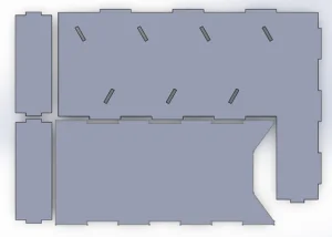
At this point I was happy with the created model; the final part of the CAD process was to save each part profile as a DXF. This is a really simple process in 3DEXPERIENCE SOLIDWORKS. You can do it by selecting DXF as the file type during the saving operation. An option box then appears asking which face of the model you want to export. This produces a 1:1 scale outline which can then be used to create the cutting paths using the laser cutting software. To save myself some time arranging DXF’s within the cutter software, I created an assembly shown below to arrange my 3D parts into the most compact area possible. I then exported this as one DXF file.
Finally, it was time to set up my laser cutter. Job one was to check mirror alignment before conducting some test cuts to dial in my settings. Once I was happy, I loaded in the 3mm acrylic material and began cutting the final designed parts. I again used 3DEXPERIENCE SOLIDWORKS to compile one DXF file containing the multiple parts that would be cut from each sheet. I did this to make to process easier rather than having to use the fiddly laser software. After an hour or so in the workshop I had all the required parts cut and laid out ready for a test assembly!
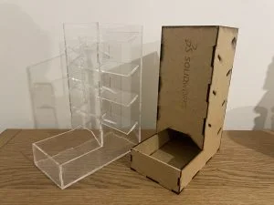
My tolerancing exercise had worked and the parts went together nicely. I added a tiny dot of superglue to each connection just to firmly lock them into place. Within 15 minutes my design had come to life, and I had my new dice tower ready to use at my next boardgame evening! At this point I thought the tower may look cool in a wooden material so I decided to cut a spare set of parts from some 3mm MDF. I think this turned out great and the engraving of the logo really pops!
I hope you enjoyed reading about how I created my homemade dice tower using 3DEXPERIENCE SOLIDWORKS for Makers. Check out the video of the design and making here!