

Hello to all,
Welcome to the new edition of the SOLIDWORKS® Support Monthly News! This monthly news blog is co-authored by members of the SOLIDWORKS® Technical Support teams worldwide. Here is the list of topics covered in this month’s Blog :
How to delete Toolbox and Partsupply component from 3DExperience Paltform?
Manage Blocks using Table States in DraftSight® Custom blocks
SOLIDWORKS® Manage Debug Mode Logs
Some ‘Must Know’ information for users when using SOLIDWORKS® toolbox.
1. How to delete Toolbox and Partsupply component from 3DExperience Paltform?
-by Bhavya JHAVERI
In the latest R2023x FD02 update, SOLIDWORKS® users can now delete data from standard libraries like PartSupply and Toolbox. Attached is a short workflow video of a component which is no longer required and is deleted using the Collaborative Lifecyle application widget on the 3DEXPEREINCE Platform®.
Please note, there are certain rules for deletion of the objects:
- To delete a Toolbox or PartSupply component, you must have Leader You can refer to the user assistance for Leader Responsibility to learn more about the operations that you can carry out.
- The component that you want to delete must also be in either the InWork or Private maturity state. When you insert a standard library component into an assembly, the component is saved to the common space (regardless of the space that is currently active) and the maturity state is set to Released. Therefore, you must change the maturity state to InWork before you can delete the component from Collaborative Lifecycle.
You can also delete a Toolbox or PartSupply component using the Collaborative Lifecycle from the MySessions App in the task pane as well.
For more information on how to delete Toolbox and PartSupply components thourgh the MySession app in the task pane, please refer to the detailed workflows in the Wiki on 3DEXPEREINCE Platform User’s Community for both SOLIDWORKS Connected Standard and Collaborative Designer for SOLIDWORKS.
From R2023x FD03 onwards, the open and save performance of assemblies containing Toolbox components has been improved. This is because the components are now verified and saved at the same time as the assembly is being saved. This was not the case in previous versions.
2.Manage Blocks using Table States in DraftSight® Custom blocks.
-by Gauri JAGTAP
It is tedious job to work with the large drawing containing number of Custom blocks where we are required to perform number of actions. DraftSight® Block editor has functionality to define, modify and control the activities of these blocks reducing number of actions required otherwise. We use Custom Block Elements and Element Sets for these activities.

- Custom Block Elements specify the entities that are required to perform associated activities. Special grip points are displayed on the Block geometry. We use the grip points to manipulate the Block reference outside the Block Editor.
- Activities help us to define the actions associated with defined elements.
- Element sets are predefined sets of elements and activities that can be used together. An element set places an element along with an associated activity to each grip point of the element.
How to use these functionalities? Let us see.
Here we are going to learn about the option Table Set from the Element Sets with the example. Using Table Sets, we can create single custom block for different views using drop down list as we insert the block in graphics area.
Steps to add Elements and create Table Set:
Let’s say we have a rectangular Block as shown in below image and we have to rotate this block at one vertex.
- Select newly created block and type command ‘EditBlock’ to start block editing or double click on Block to open Editing Window.
- Go to Elements > Rotation and specify a point which will act as a rotation point for the custom block with radius element and specific angle (e.g., 30). Give a Grip point.
- Now in Activities, select ‘Rotate’, then select the element we have defined in step 2 and select the block as Entity to Rotate.
- Now, select the element and follow below steps.In Properties Palette we will add the details required for the rotation activity.
- In Misc, Chain Activities, select ‘Yes’. (Specifies whether we want to include the element in the selection set of an activity that is associated with a different element.)

- In ‘Value Set’ (Specifies a set of values that we can assign to the element in the Block reference.) Change ‘Angle Type’ to ‘List’ (Specifies a list of values that are available for the element in the Block reference). Click on the ‘…’ of ‘Angle Value List’

- It opens ‘Value Set List’. Add different Angles needed for rotation of Block. I have given 30 (given in step 2), 40,50,60. Click on ‘OK’.

- In Misc, Chain Activities, select ‘Yes’. (Specifies whether we want to include the element in the selection set of an activity that is associated with a different element.)
- Select option ‘Table Set’ from ‘Element Sets’ and click at some point. It adds a table element with one grip point and a table activity.
- Give command ‘_CBVALUETABLE’ (CBValueTable command helps to display or update the value table associated to a table activity in a CustomBlock definition) in command window and specify Table element we created in step 5. It opens Property Value Table. Click on ‘Add Properties’ > Angle-Rotation row > OK. On clicking in the rows below ‘Angle1’ column, it gives list of all the angles we have set in step 4. Make a row for each angle with some notation as shown in the image. It gives us Table States. Click on ‘OK’.

- Exit the Block Editor after saving these changes. When we select the block and click on the grip point of Table Set, we will get the drop-down list with Table States. As we change the states, block will rotate at the element point we stated in step 1.

This way we can manage custom blocks combining multiple activities in drawing effectively. It is a very efficient way to save time.
3.SOLIDWORKS® Manage Debug Mode Logs
-by Rohit MAGAR
In order to speed up the troubleshooting process, use the SOLIDWORKS® Manage Database Debug Mode which can produce a log file that can be examined by the support team. The user must enable database debug mode, and the log will record the previous 100 SQL Database queries.
In the Administration tool, for Audit Trail, administrators can specify that tracked errors are written to a log file on the user’s computer. The user can then send this log file to the administrators or to the SOLIDWORKS® Technical Support team for analysis.
Enable log options for Debug Mode
SOLIDWORKS® Manage > Options > My Options
To enable the debug mode options, Goto General Tab > Log Options :
- Database debug mode
- Log File debug mode

Database Debug Mode:
With the 2021 release and later versions, administrators can access the log using the Database Debug Log Viewer. This is an advanced feature used for troubleshooting. To activate the debug log, a specific user must do so from “My Options”. Once active, this log holds the last 100 SQL Database queries (for each user). The user can manually disable this option. This option will automatically deactivate after 24 hours if not disabled by the user.
To get these logs go to SOLIDWORKS Manage > Options > Administration Options > Advanced > Audit Trail > Database debug mode (Log).
All database transactions for the selected User or Users will be displayed in the grid.
The following options are available on the right-click context menu:
Copy selected value – Right-clicking in a specific cell, allows its value to be copied to the clipboard. This is especially useful in the Log column, where the specific SQL Database queries which were performed can be copied.
Export – The results can also be exported by clicking Export.
Copy selected value and Export options are also available from the button on the left-hand side of the tab.
Log File Debug Mode: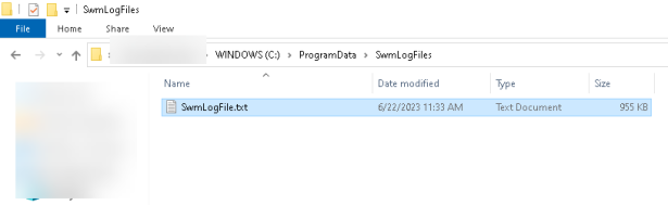
SwmLogFile
Activating the ‘Log File debug mode’ option creates a debug log file in the folder location : [C:ProgramDataSwmLogFilesSwmLogFile.txt]
4.Some ‘Must Know’ information for users when using SOLIDWORKS® toolbox.
Many a times users run into issues related to toolbox and try to diagnose them at their end. In such times its very important to know how Toolbox actually functions and what are some points to keep in mind while diagnosing them. I have compiled few of many such points which might help you in such situations.
-by Gaurav GAYAKWAD
-
Why do we see difference in number of configurations for the same toolbox parent part(within browser folder) on two different machine running SOLIDWORKS®?
- When we first install toolbox, the parent part, that is part saved in browser folder does not have any configurations. The configuration are created when the user inserts configurations of Toolbox in SOLIDWORKS®. Let’s try to understand this by an example shown in the video.
-
What does User settings option ‘Create Configuration’, ‘Create Parts’ and ‘Create Parts on Ctrl+Drag’ do?
- Many of you would be knowing meaning and the function of these option but sometimes we don’t think about these settings while facing an issue.With ‘Create Configuration’ being the default option, each time you use a new size of a particular component it adds configuration to the master part. This option has advantages that we don’t need to create part file with each size but on the other hand the master part file gets larger with each new size and then if you use that as separate file, there might be configurations which are created and has no use for that assembly and just affecting the performance. The option ‘Create Parts’ creates each part for different sizes, with this you will get number of smaller part files but many of them which makes it difficult to manage but it eliminates the behavior of ‘Create Configuration’. The option ‘Create Parts on Ctrl+Drag’ is combination of two, when user does normal drag it behaves like ‘Create Configuration’ and with Ctrl-drag, behaves like Create Parts.

- Many of you would be knowing meaning and the function of these option but sometimes we don’t think about these settings while facing an issue.With ‘Create Configuration’ being the default option, each time you use a new size of a particular component it adds configuration to the master part. This option has advantages that we don’t need to create part file with each size but on the other hand the master part file gets larger with each new size and then if you use that as separate file, there might be configurations which are created and has no use for that assembly and just affecting the performance. The option ‘Create Parts’ creates each part for different sizes, with this you will get number of smaller part files but many of them which makes it difficult to manage but it eliminates the behavior of ‘Create Configuration’. The option ‘Create Parts on Ctrl+Drag’ is combination of two, when user does normal drag it behaves like ‘Create Configuration’ and with Ctrl-drag, behaves like Create Parts.
-
While adding a new custom size for any of the toolbox component. Why do I see rebuild error after inserting it into the assembly? An Image of the error show below.

- One of the reasons for these errors could be due to mismatch in the format of digits between different fields of the entry. I mean when the user has created this size he has not followed the format of digits for specific columns. In the image shown above the user has specified the ‘Pitch’ as ‘2’, where as it should be ‘2.0’. You can know this if you see the default entries. Please see below image for clarification.

- One of the reasons for these errors could be due to mismatch in the format of digits between different fields of the entry. I mean when the user has created this size he has not followed the format of digits for specific columns. In the image shown above the user has specified the ‘Pitch’ as ‘2’, where as it should be ‘2.0’. You can know this if you see the default entries. Please see below image for clarification.
-
How to identify if the issue is due to corrupt Toolbox?
- The corrupt toolbox can cause multiple issues, and error message might not necessarily point towards anything specific. In one of the such cases the issue was that the user has created some custom sizes tapped holes in Hole Wizard but while inserting in the part it shows ‘Thread data not found for ‘<custom>’ size’. When you open the Toolbox and go to the Tapped Hole page you will notice ‘Sort Order’ column is a checkbox whereas when you compare it with any default toolbox you will notice it should be a place to insert a number (integer value). The cause of this corruption is unknown. This also prevents modifications like adding new sizes to the Hole Wizard in the particular standard. You can see the image below for reference. In order to get this repaired you need to send the toolbox to Technical Support.

- The corrupt toolbox can cause multiple issues, and error message might not necessarily point towards anything specific. In one of the such cases the issue was that the user has created some custom sizes tapped holes in Hole Wizard but while inserting in the part it shows ‘Thread data not found for ‘<custom>’ size’. When you open the Toolbox and go to the Tapped Hole page you will notice ‘Sort Order’ column is a checkbox whereas when you compare it with any default toolbox you will notice it should be a place to insert a number (integer value). The cause of this corruption is unknown. This also prevents modifications like adding new sizes to the Hole Wizard in the particular standard. You can see the image below for reference. In order to get this repaired you need to send the toolbox to Technical Support.