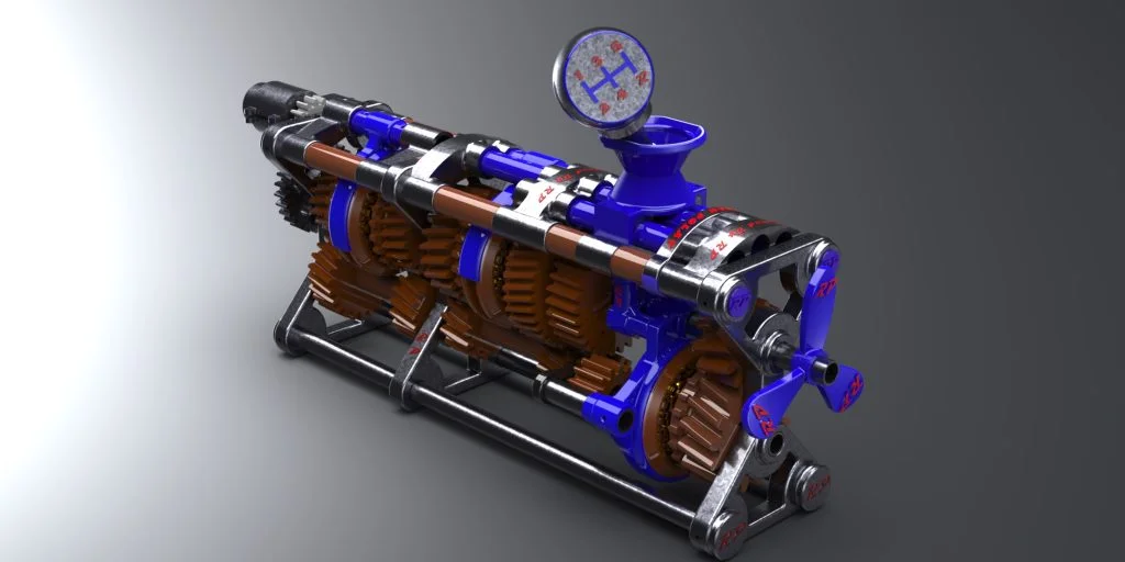

While studying Automotive Engineering at the university, I designed a Gearbox with Locked Synchromesh as my internship assignment and produced it using a 3D printer. I designed the Gearbox using SOLIDWORKS. When I discovered the world of 3DEXPERIENCE, I wanted to make improvements in my design. These improvements were focused on shortening the printing time. Of course, while doing this, I wanted to keep the durability at the same level. I learned that I can use Design Guidance to do all these things.
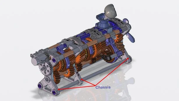
In this tutorial, we will use a feature of xDesign in the 3D Creator role, namely the Design Guidance, to make the Chassis lighter and more durable.
First, let’s learn the basics of Design Guidance together.
What is Design Guidance?
The Design Guidance is a design tool for creating the design of a new part or testing and recreating the design of an existing part. The shape created with Design Guidance is created according to the loads and constraints we specify on the sketch or 3D model.
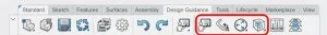
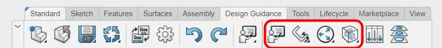
There are many command in the Design Guidance menu. Throughout this tutorial we will see the commands marked in the picture.
Learning Assistant
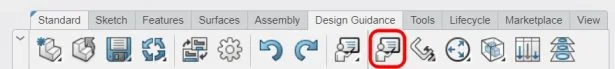
With this command, you can take a quick tour of both the xDesign interface and the Design Guidance interface.
Restraints
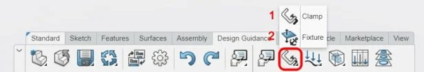
1. Clamp: Constrains all movement (in the X, Y and Z axes) of the selected plane or surface.
2. Fixture: Constrains the movement of the selected plane or surface in one or more directions. Allows the selected plane or surface to slide freely outside of constrained directions.
Loads
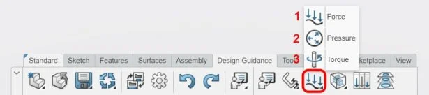
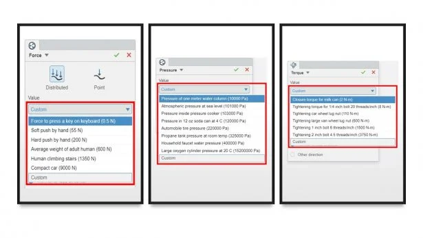
1. Force: You can use force to simulate push or pull energy. Force can be applied to the selected plane or surface in two ways.
a. Distributed: With this option, you can distribute the force evenly on the surface.
b. Point: With this option, you can apply the force to the center of the selected surface.
2. Pressure: You can apply forces perpendicular to the unit surface area or apply atmospheric pressure.
3. Torque: You can use torque to simulate torsional or rotational motion.
Since Design Guidance has a user-oriented interface, it also includes some ready-made values. In this way, the user can quickly determine the value they want to apply.
New Design and Redesign
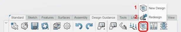
1. New Design
It creates a 3D model according to the loads and restraints we specify. You don’t even need to have a 3D model when using this feature. We’ll be using the New Design command throughout this tutorial.
2. Redesign
Redesign, on the other hand, allows us to test the accuracy of the design according to the loads and constraints we have specified on an existing 3D model. We can liken this feature to the topology optimization in SOLIDWORKS Simulation.
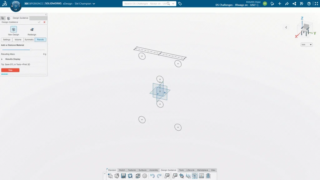
Now that you have obtained a lot of information about Design Guidance, we can move on to our project.
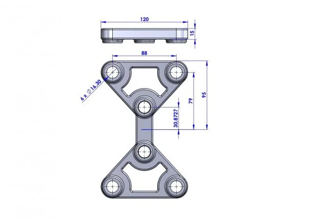
Step 1: Technical Drawing
We will use the New Design command in the Design Guidance. For this, we need some 2D drawings and dimensions on the Chassis. We can obtain these drawings and dimensions from SOLIDWORKS. For this, I created the following technical drawing by following the necessary steps.
Step 2: Creating a 2D drawing in xDesign
In Design Guidance, you need a surface or a plane to apply a restraints or a load. In this study, we will use planes.
In the xDesign login screen, we create a new component called Chassis.
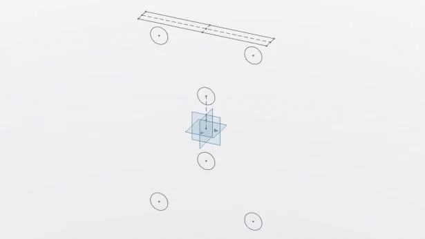
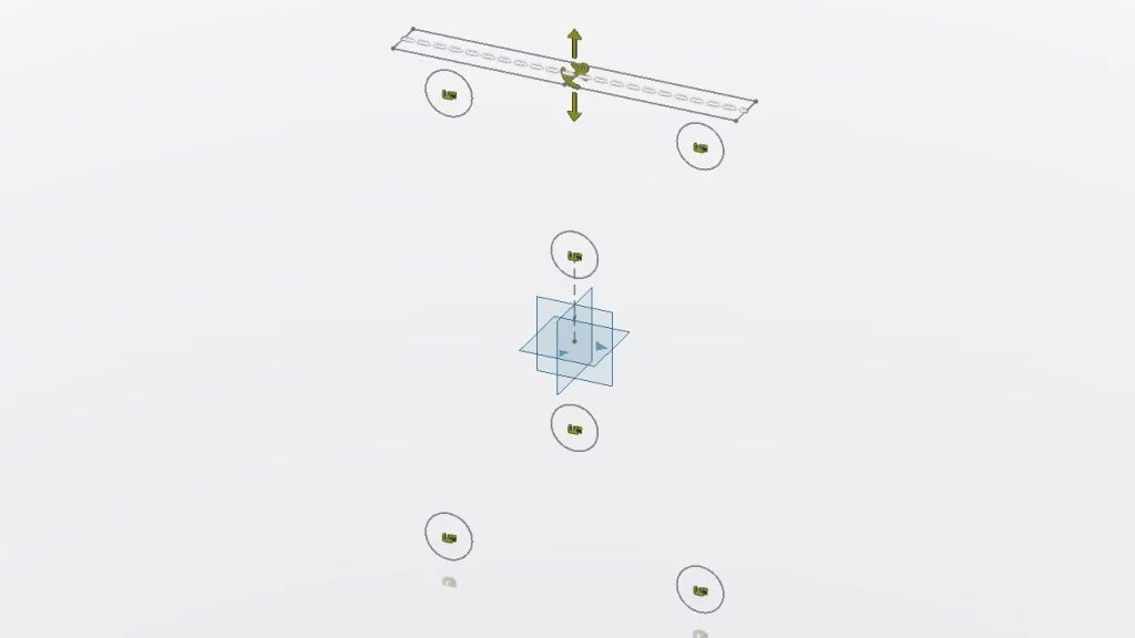
We create a new plane parallel to the YZ plane and at a distance of 0 mm. By opening a new sketch on this plane, we draw the holes shown in the front view. We confirm the sketch.
We create a new plane at a distance of 95 mm parallel to the XY plane. We open a new sketch on this plane and draw the rectangle shown in the top view. We confirm the sketch.
It will now look like the following.
Step 3: Restraints
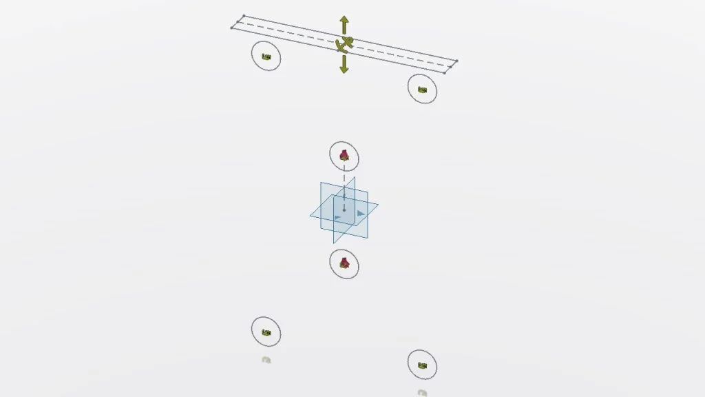
We need to restrict the movements of the 6 holes we created on the YZ plane in the X, Y and Z directions. We will use the Clamp command for this. After clicking on the clamp command, we select the holes and confirm the command window.
The rectangle we created on the XY plane will form the thickness of the chassis. We only need to make a downward constraint. Here we will use the Fixture option. The reason why we do not use clamps is that we do not want to create a 3D geometry that connects to the XY plane. After clicking the Fixture command, we select the rectangle and confirm the command window.
It will now look like the following.
Step 4: Loads
The outermost 4 of the holes on the chassis carry the fixed parts of the chassis. Since these parts have very low masses, there is no need to apply loads to these holes. The 2 holes inside carry the moving parts. The shafts on which the gears are mounted are connected to these two holes. For this reason we will apply force and torque loads to these two holes. In this project, I determined the factor of safety as 2.
Force
2.5 kg x 9.81 m/s^2 x 2 = 49.05 N
Torque
7.2 Nm x 2 = 14.4 Nm
After clicking the Force command, we select 2 holes and enter the force value as 49.05 N in the relevant place. After determining the force direction downward, we confirm the command window.
Since the rotation direction of the gears is different, we will apply the Torque command to both holes separately. According to the middle plane, the hole at the top moves clockwise and the other one moves in the opposite direction. After clicking the Torque command, we select the top hole and enter the torque value as 14.4 Nm and confirm the command window. We repeat the same operations for the other hole by changing the direction of rotation.
It will now look like the following.
Step 5: Material
The default material in xDesign is ABS plastic. You can use the Material Browser in the Tool menu for a different material selection. In order to give an example in this project, how the material assignment is made is shown in the related video.
Step 6: New Design
The New Design command has many tabs and features. After clicking the command, we will make the following adjustments.
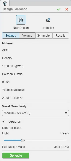
- In the Voxel Granularity section in the Settings tab, we select our thawing detail as Fine.
- We determine the target mass from the Desired Mass section.
- From the Volume tab, we create a bounding box to include our drawing geometry. By clicking on the Generate box, we enable Design Guidance to create the most suitable Organic model for us.
- When the Organic model is created, we can set the required mass from the Result tab as we want.
We confirm the command.
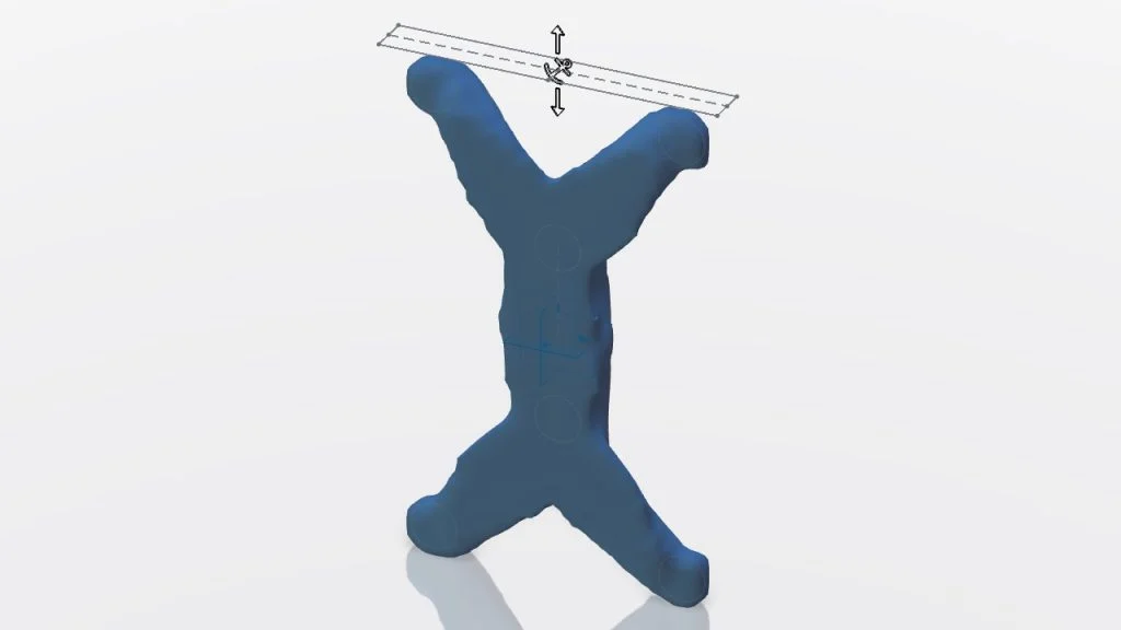
It will now look like the following.
Step 7: Parametric Design
Design Guidance created an organic model as a result of the calculations. In order to make this model ready for production, we create and save a parametric model with reference to the model.
Our model looks like the following.
Step 8: Slicing Model
Before using Design Guidance, the print time of the model was 9 hours and 40 minutes. The printing time of the model we created using Design Guidance is 7 hours and 16 minutes.
Thanks to Design Guidance, we have accelerated production by 25% in a period of 2 hours and 24 minutes.
Step 9: SOLIDWORKS Connected
Finally, I will include the part we designed in xDesign using SOLIDWORKS Connected in the gearbox assembly. Since SOLIDWORKS Connected is directly connected to my storage in the cloud, I searched for my part by name and dragged it to my assembly environment. We performed the assembly quickly with the quick assembly commands.
In this tutorial, I detailed the value of the Design Guidance feature. See you in the next training