As mentioned in the first part of this blog post, a backup manifold needed to be designed and built in time for Round 7 of the FD season. The schedule left approximately 48 busy hours for design and programming of the CNC cut manifold parts to be done in Canada. Another 48 hours remained for the talented staff at Full-Race in AZ to digest the 2D prints, 3D print the fixtures, cut the parts, and create the first prototype fabricated manifold before shipping it to Papadakis Racing in California.
Start of Fabricated Manifold
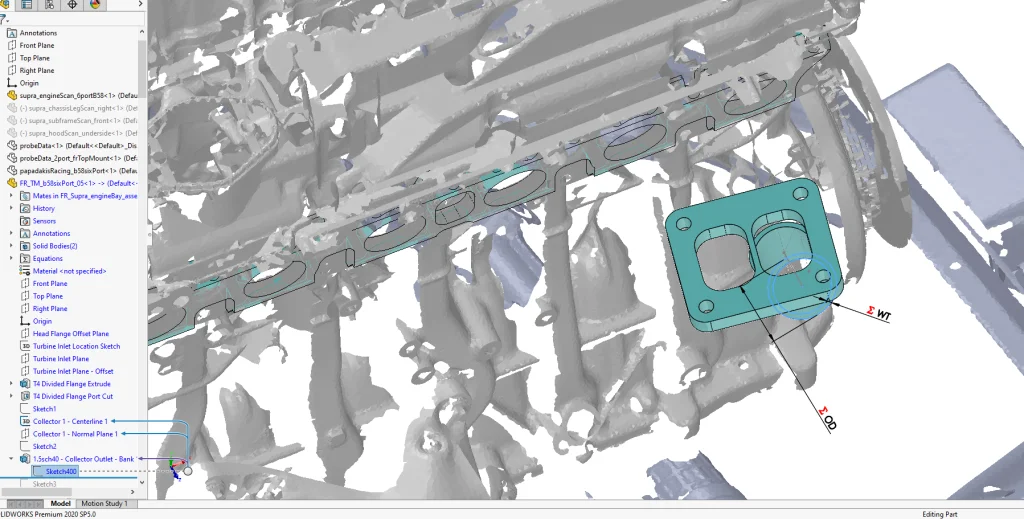
In the interest of time savings the goal for the fabricated manifold was to follow a similar collector, wastegate and runner layout/routing to the additive manufacturing manifold, in fact the Part File for the AM was saved as a copy with a new name to retain the same initial layout sketches.
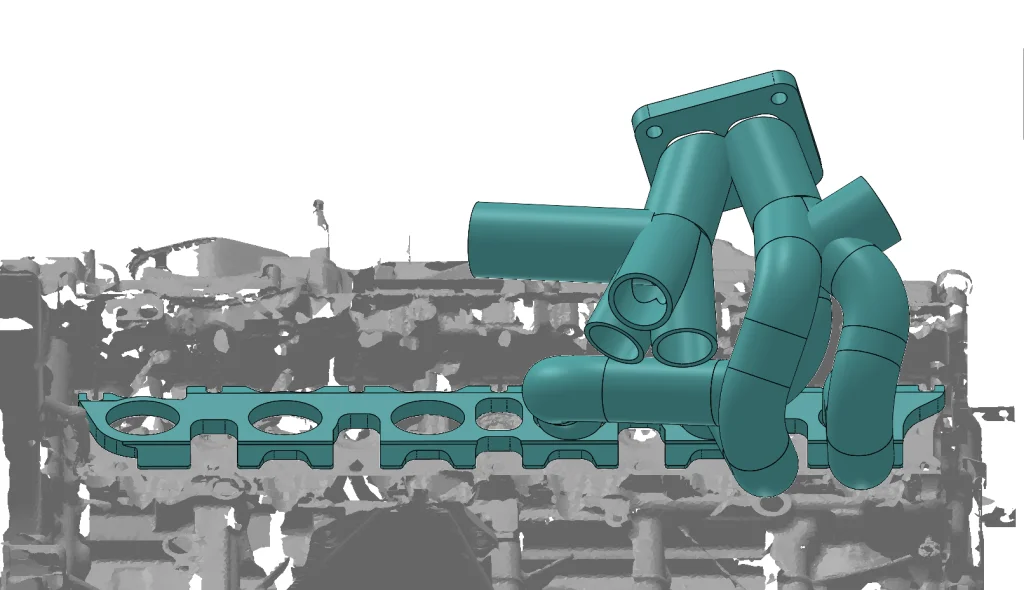
The 3D Print design allowed for nearly unlimited freedom regarding sizing, shapes, and layout. A fabricated manifold requires the use of standard pipe sizes including diameter, centerline radius and bend angle. This time the first step was to create a solid body for the turbine flange. This represented a standard flange that Full-Race keeps in inventory for a wide range of manifolds.

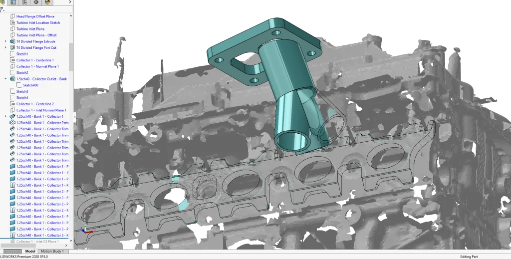
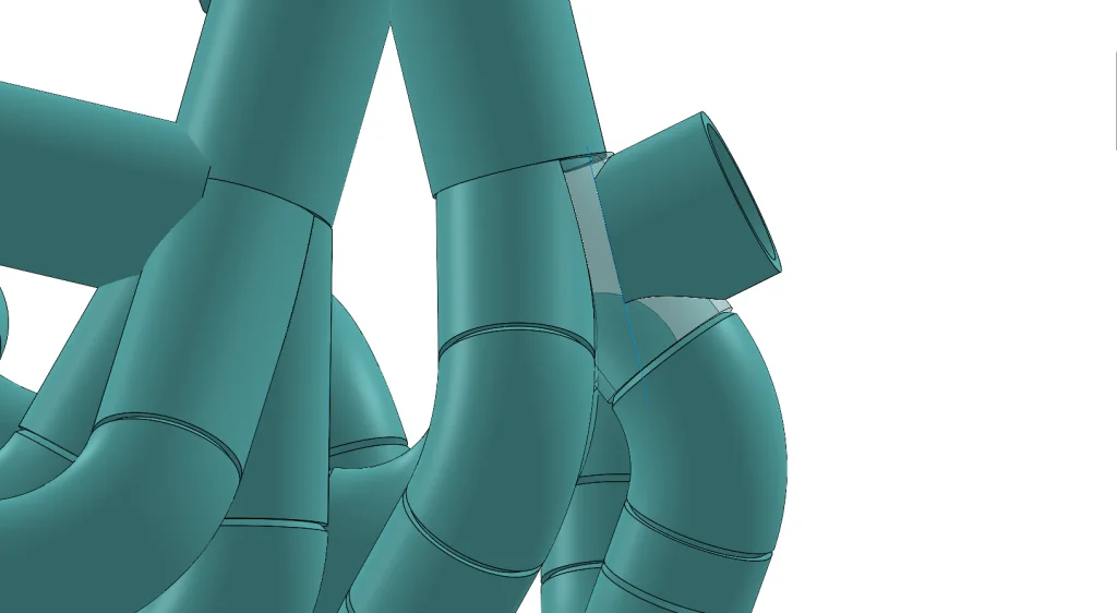
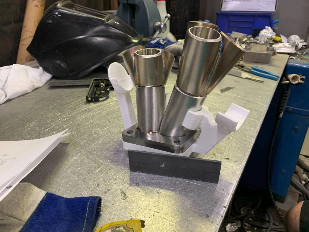
Although the turbine flange position remained the same, the original collector centerline sketches were modified to suit the new manufacturing method. In this case the manifold sections were modelled using Solid Extrudes and Solid Sweeps. The pipe specifications such as outer diameter, wall thickness and bend centerline radii were set up as Global Variables so they could easily be added to sketches and adjusted should a different pipe be needed. Transitions between pipes and flanges were not modelled for this manifold (as seen above, the round pipe has gaps around the rectangular port shape). The individual pieces were CNC cut as modelled and hand formed to their final shape where needed. The end result is a smooth transition not extremely different from the AM transition.
Care needed to be taken to ensure good fit between manifold pieces to minimize frustration for the welders and maximize weld quality and strength.

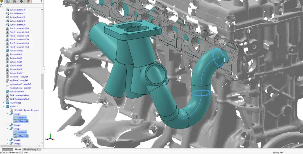
Where complicated joints and pipe intersections needed to be created (the collectors) the preferred method was to use Extruded Surfaces so that the shape could be precisely trimmed and knit into individual bodies.
This time the selection of the wastegate locations was started earlier in the design process due to having less design freedom. However, details like wastegate runners and collectors were continually adjusted over the course of the design process.
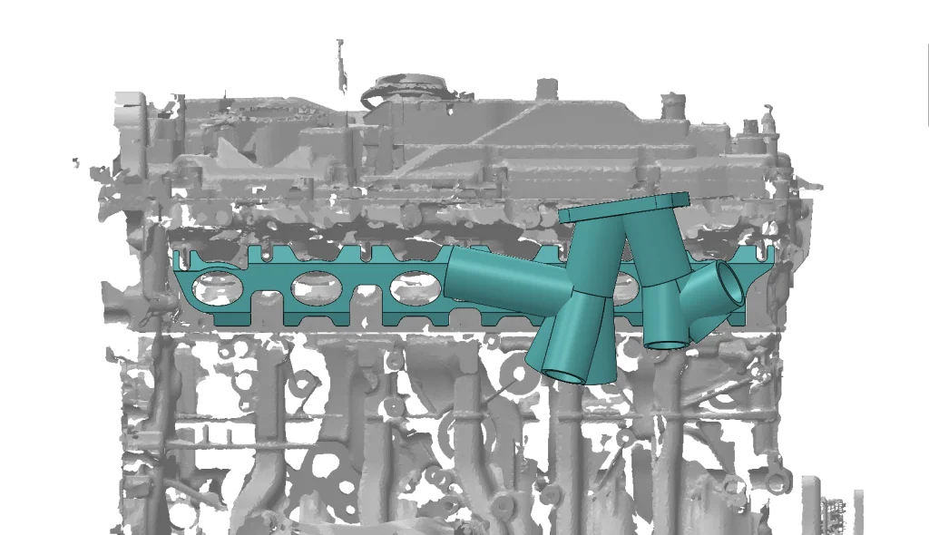
Once again, the runner is designed using 3D Sketches, however they can only contain Arcs and Line Segments. These sketch components represent the pipe segments being used. The final sketch looks simple but it takes time making a centerline that adheres to the selection of centerline radius and bend angle, and also remains tangent from start to finish. Maintaining tangency is more work during design but it will reduce the amount of hand finishing required by parts, as well as guaranteeing smooth runners. 3D Sketches are fully defined to ensure every piece is done with intention and nothing is overlooked.
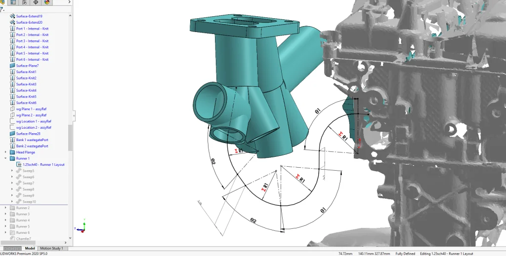
Runner segments are done with individual Swept Bosses which are kept as separate bodies. It is possible that SolidWorks weldments could be used for this design style, however I have found that this method works well for my workflow for sending the pieces to the CNC CAM software.
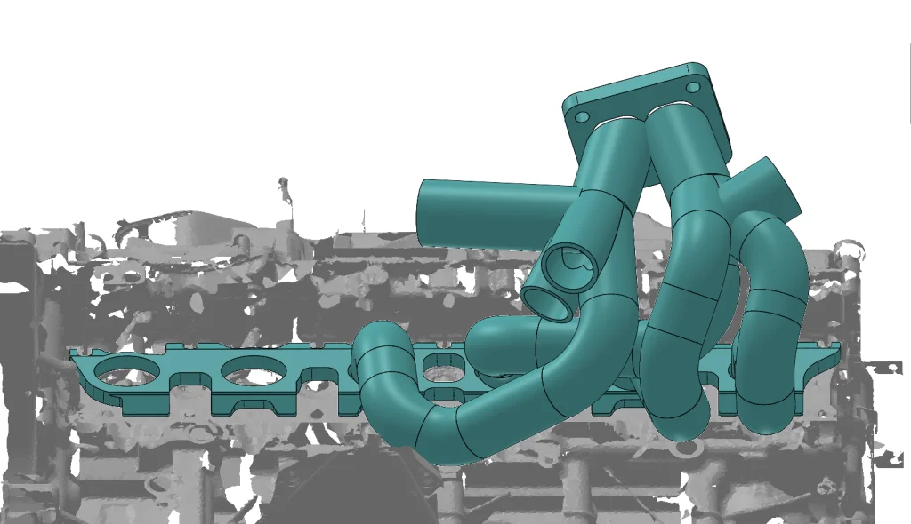
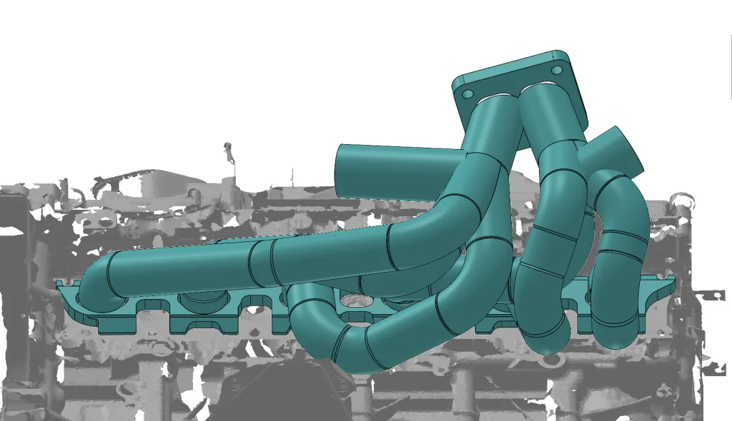
The above process is repeated for runners 2 – 6. Chamfers are added to the weld joints; however, this was done more for visual effect as any chamfers needed are added by hand by the fabricator.

Cut features were added for the wastegate runners.
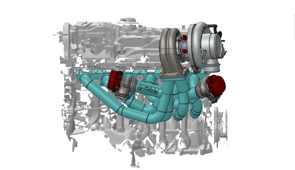
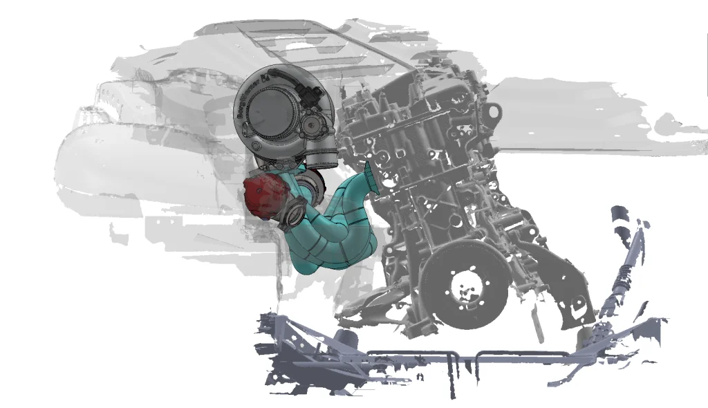
Finally logo placement was selected and a final check was done with supplier CAD to verify fit with the scan data.
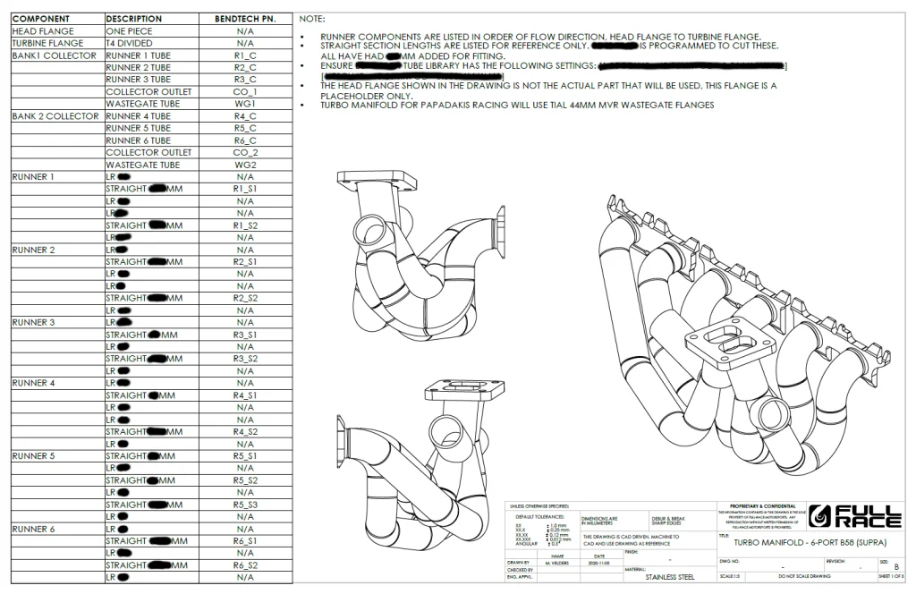
The last part of my involvement in the project was to create a 2D drawing package that contained a BOM for the order of the components used for each runner and to provide a visual reference of the layout. As well as the design of a temporary fixture that could be 3D printed to build the collector as well as locate the collector in relation to the head flange.
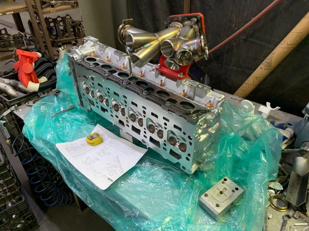
Once the collector was finished the runners were built.
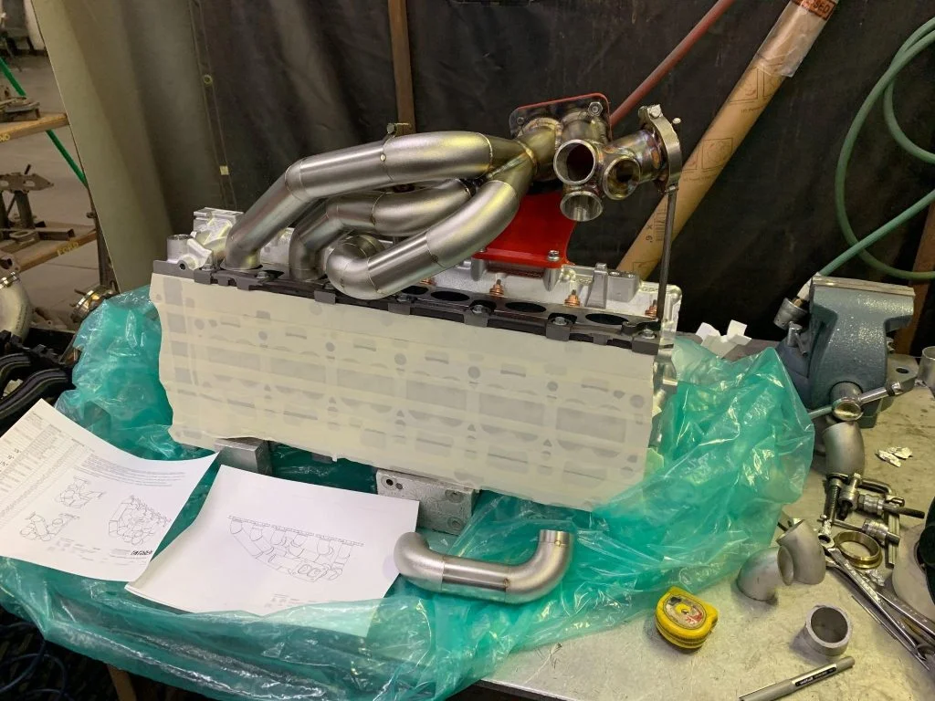
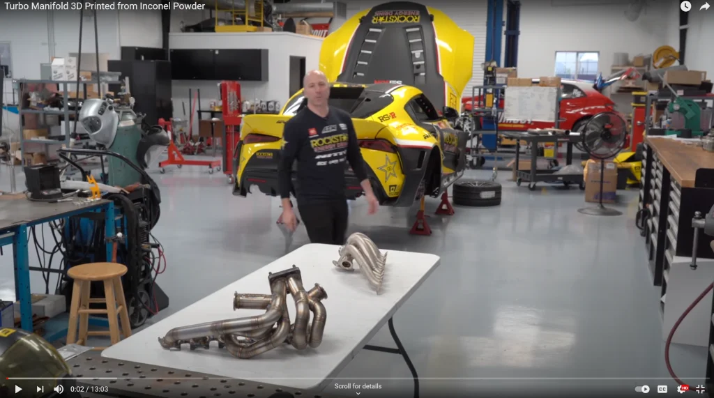
With the robotically TIG welded runners and finish welding complete the manifold below was the final result.
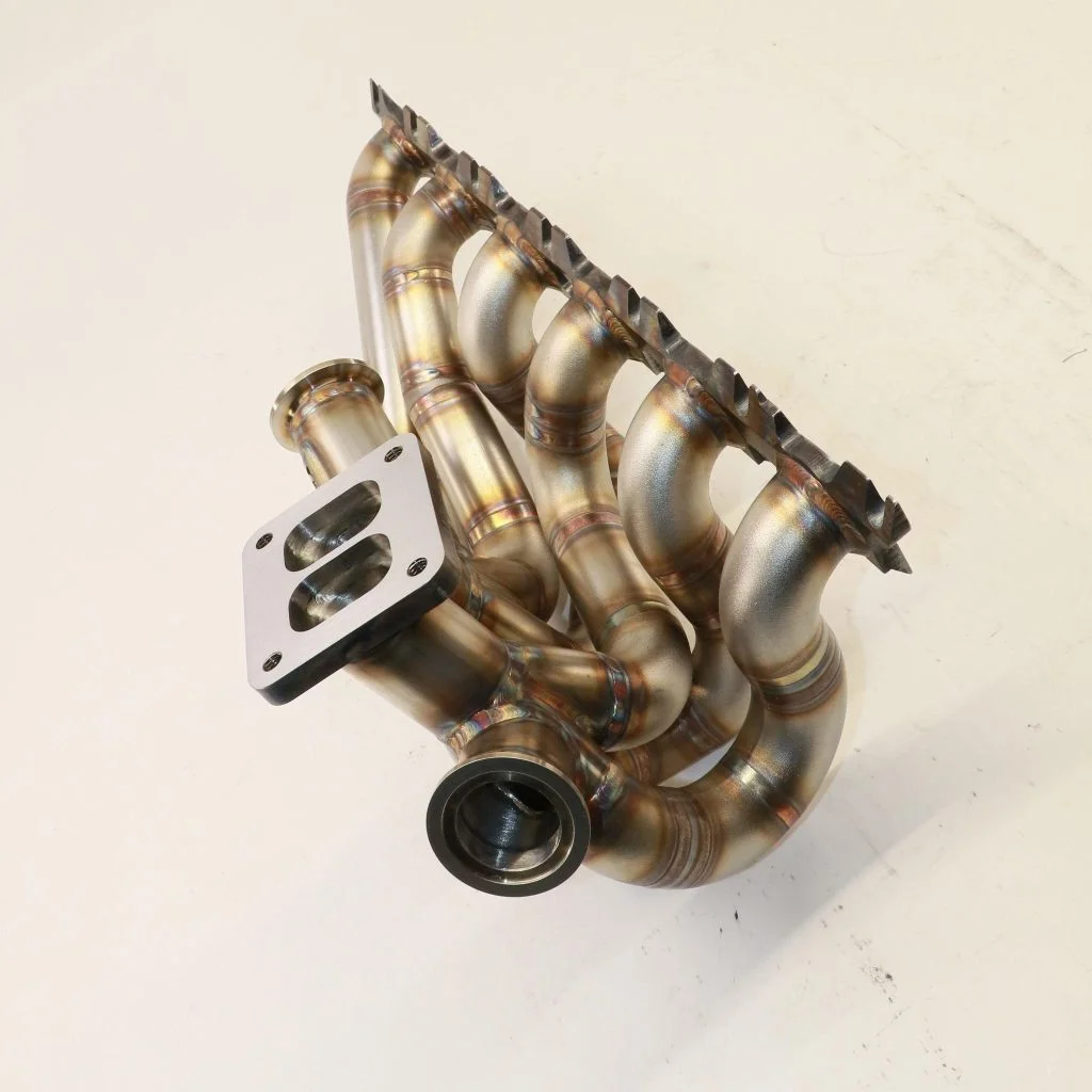
End of Fabricated Manifold
With the competition car strapped to the dyno, new fabricated manifold installed, the engine was mapped and final power figures were measured… to see if the new setup had resulted in the lost power we were all hoping for. I won’t make you hold your breath in anticipation… It did. The car gained power everywhere (red lines below). It made max figures of 995 hp and 840 lb∙ft of torque. A power and torque increase of 15% and 20% respectively (all figures are without the use of nitrous oxide).
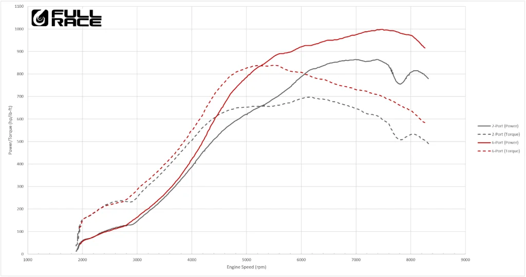
As exciting as the peak power and torque gains were, it was more exciting to see that the engine made more power and torque from aprrox. 2750 rpm to the rev limit. In this day and age of hyper competitive turbochargers – it’s rare to find huge no-compromise power gains. But they were here; earlier turbo spool, an increase in area-under-the-curve and faster turbocharger response. Win/Win/Win. We also proved wrong the theory that a 2-Port head might outperform the 6-Port head in the lower engine speed range.
Other areas of interest on the above dyno plot is the area around 5200-5300 rpm where the engine is now making 27% more power than before, as well as the elimination of the dip in power around 7800 rpm. At that point the engine is making 30% more power and the elimination of that dip creates a smoother powerband that will help Fredric’s sense of feel for the car’s behavior. This enhances his ability to control the car, a crucial factor in a sport where the driver with the most accurate car control often wins.
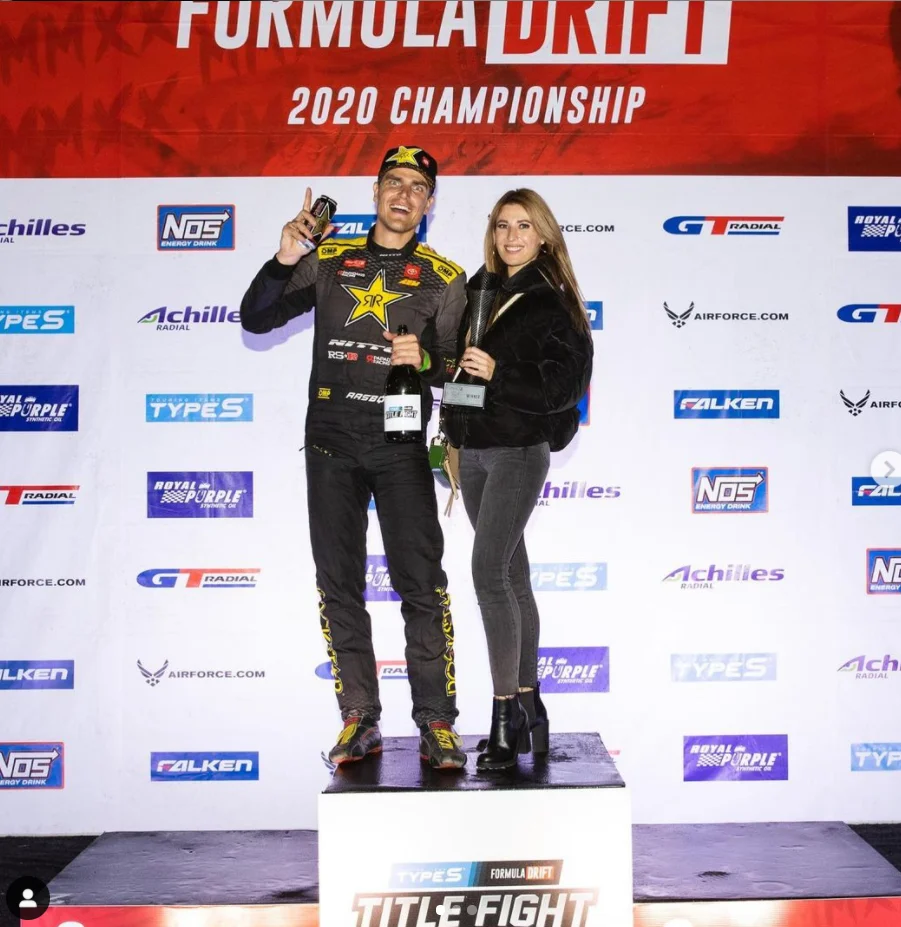
And win he did. With nitrous oxide pushing the car to 1100 hp Fredric was able to pilot one of the most powerful cars of the field to another 1st place finish at Round 7 of competition. Unfortunately, the extra power also helped find the next weak link in the engine package. Fredric therefore dropped out of Round 8 leading to a 4th place finish in the 2020 season. It was a thrilling start for a new chassis and engine combo however, and we can’t wait to see how Fredric Aasbo and Papadakis Racing do in the 2021 Formula Drift season. And what tricks we will be able to apply through development and technology.
I hope you enjoyed this look into the development process for a fun and very unique turbo manifold project. The Full-Race team is thrilled to work with 3DS and deliver insights to the CAD and car enthusiast communities alike.
Also, be sure to watch the “Turbo System Design – 3 Mistakes the Aftermarket Industry Makes” webinar to learn more.