This is the first blog post of a series, so make sure to sign up to the mailing lists if you want to see how our partners at SOLIDWORKS, Creaform and Jabil Inc. are helping us to bring new ideas to life and build more value in the products we create. I’m Mathew Velders. I run product design engineering at Full-Race Motorsports in Phoenix, AZ. We’ve been in business for 18 years and the only thing we talk about every day is turbocharging. Our customers want to blast down a track at the fastest possible speed…as much as their hardware, and physics, can allow.
Over the years we’ve formed an amazing set of partners. From major automakers and OEM suppliers to professional race teams, we’re helping professionals make the right decisions about turbochargers. We have arrangements with major OEM manufacturers. That lets us keep prices low. And we can source any turbocharger a customer needs (plus, we crunch the numbers for them).
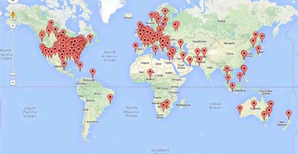
Now, we’re a small company. But every day, we help someone, somewhere, with these calculations. And with customers in 100 countries around the world – we’re super dedicated to making happy customers.
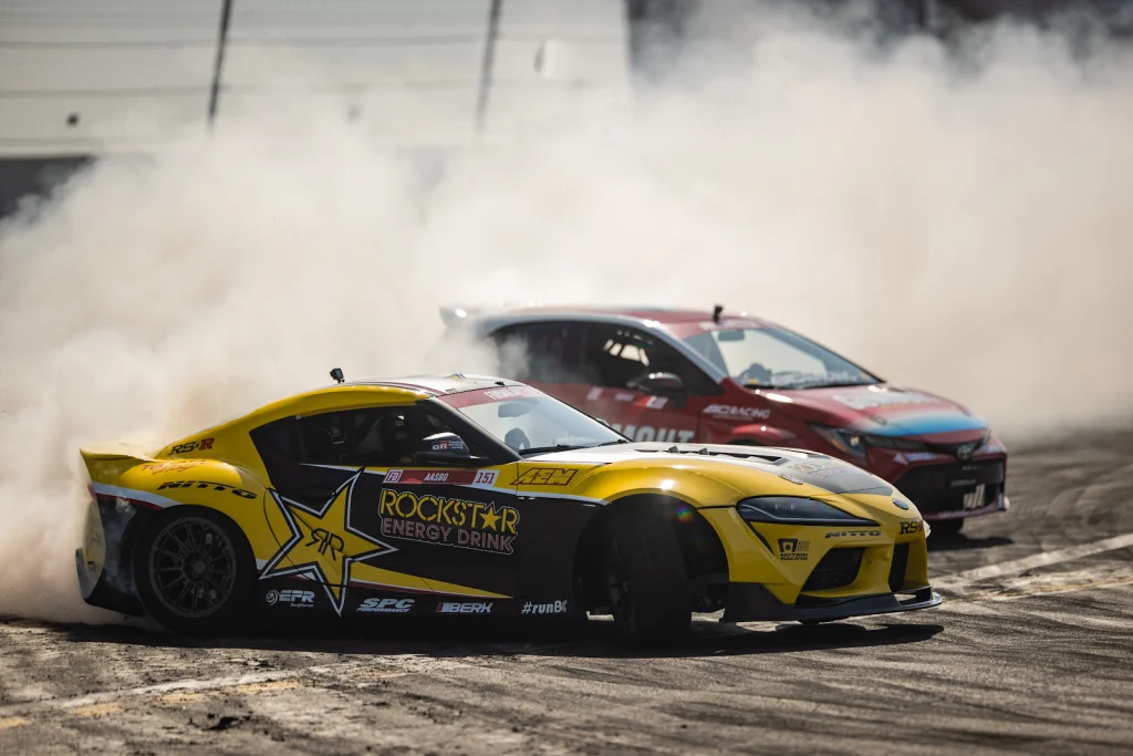
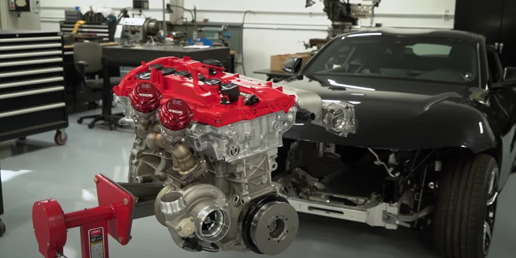
Over these last 2 decades, we’ve seen the thinking change about turbochargers – and the tools used to design them. For the last 10 years, since the debut of BorgWarner’s twinscroll EFR turbochargers – Full-Race supplied turbo systems to Papadakis Racing, the most winning drift team in history. While preparing their Toyota Supra for the 2020 Formula D season Papadakis Racing turned to us for the turbo system to achieve 1000hp with their “2 port” B58, 3.0 liter, inline 6-cylinder engine.
The turbocharged B58 engine in the 2020 Supra utilizes a Twin-Scroll manifold/turbine design to produce 335 horsepower and 365 lb∙ft of torque. Twin-Scroll means that the engine’s cylinders are grouped into a pair by their firing order. In the case of the B58, cylinders 1-2-3 are grouped together to flow into the first scroll, or volute, of the turbine; cylinders 4-5-6 are grouped for the second scroll of the Twin-Scroll arrangement. This grouping of cylinders greatly reduces the exhaust pulse interference in the turbine entry. Rather than a single grouping of six cylinders paired in one scroll with an exhaust pulse every 120° of engine rotation, there are two groups of three with a pulse every 240°. This means there is a smoother, consistent delivery of energy to the turbine shaft of the turbocharger, resulting in better turbine response and engine power. While the Twin-Scroll layout is not new, the application of it in this engine uniquely uses an IEM (integrated exhaust manifold) incorporated into the cylinder head of the engine. This means the 6 cylinder engine only has two exhaust outlets, one for cylinders 1-2-3, and one for 4-5-6. These outlets flow almost directly into the two scrolls of the exhaust turbine.
This is done on modern vehicles to simplify component packaging, reduce ‘turbo-lag’ and help meet emissions requirements but it could be a bottleneck when chasing the massive horsepower levels required to win a Formula Drift championship.
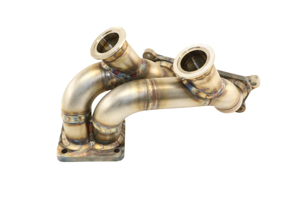
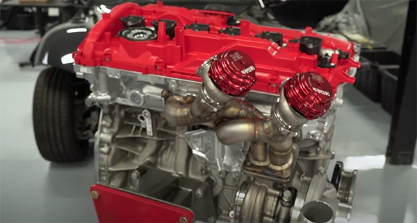
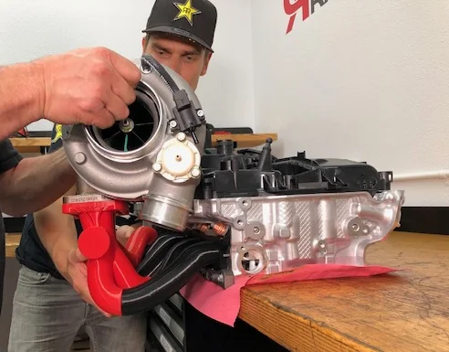
Full-Race constructed our ‘top mount’ turbo manifold to suit the 2-Port Supra’s cylinder head and unique chassis. The turbo manifold connects the turbo to the engine, and is the foundation for the entire turbo system.
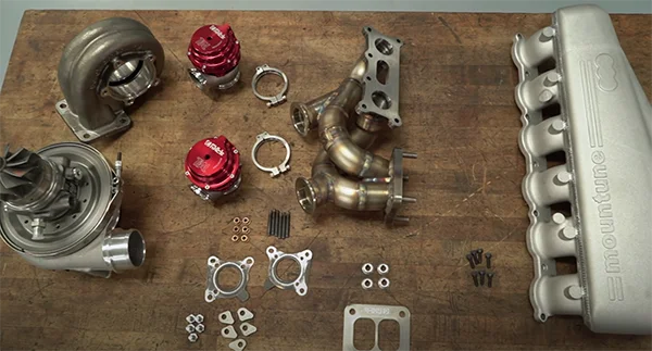
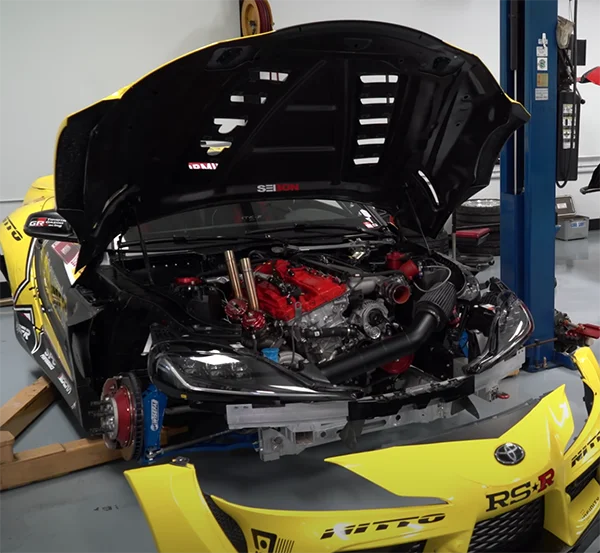
It had to fit a massive turbocharger like the BorgWarner 9280, rated for 110 lb/min of airflow and featured two ports for twin TiAL Sport MV-R external wastegates. We got on the dyno and managed 1000hp@38psi (with nitrous oxide). The first time out with a brand new car – our Full-Race turbo system allowed driver Fredric Aasbo to win the first round of the season.
These results were promising; however, Fredric and Papadakis Racing are in it to win championships and they need more than just ‘promising’. The engine in the Supra was producing approximately 860hp without nitrous, and while this sounds like a mind altering level of power to the average enthusiast, it wasn’t enough to win a championship in a field of cars regularly producing 1000hp (and some competitors running close to 1200hp).
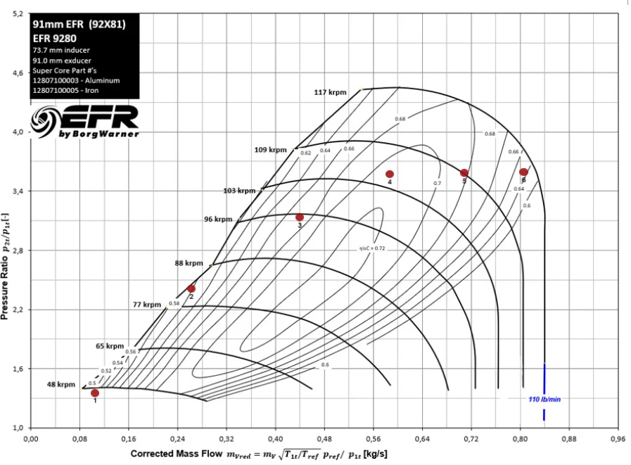
It was clear to Full-Race and Papadakis racing there was a lot more power left on the table – considering the massive 110lb/min airflow rate of their BorgWarner EFR 9280 turbo. This lack of power was a problem. And to make matters worse the final two rounds of the 2020 Formula D season were being held at Irwindale Speedway, a track favoring big horsepower.
As mentioned previously, it was suspected that the two exhaust port cylinder head represented a flow restriction that prevented the engine from generating >1000hp off the bottle. Fortunately for Papadakis Racing, Toyota was in the process of releasing their updated Supra for the 2021 model year. The new car featured better engine performance, 382 hp and 368 lb∙ft, thanks to a new cylinder head and exhaust manifold design. This time the cylinder head featured a traditional six port design – one port for each cylinder.
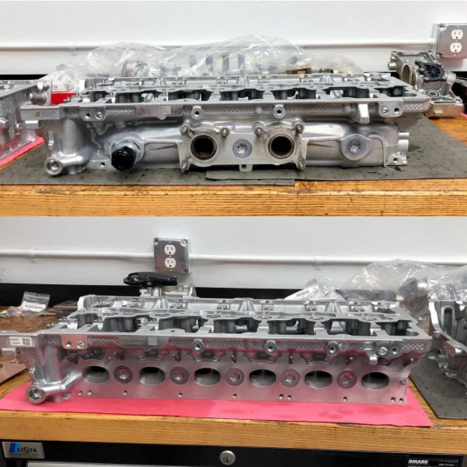
Swapping to the new cylinder head proved to be surprisingly simple. All of the components were compatible with the previous version; we used the same valves, valve springs, sensors and hardware. The only massive change required was the new turbo manifold. One that would keep the flow from all six cylinders completely separated until right before the turbo charger – where a smooth merge collector could efficiently combine the flow from the two groups of cylinders.
Full-Race was called on to create the new manifold but the situation was complex. There was only 5 weeks before the final two events of the season, COVID-19 was in full swing, the car was in California, Full-Race Motorsports in Arizona, and myself the design engineer in British Columbia Canada. Thankfully this was the exact type of situation that Dassault Systemès had in mind when they were developing their new 3D Experience platform/SolidWorks Connected. They stepped in and set Stephan Papadakis and I up with a cloud connected CAD software package that allowed us to collaborate in real time through a shared project environment. This environment allowed us to collaborate on design ideas, project scheduling, task management and generally streamline project management between teams scattered around North America.
This leads us to the part that my fellow CAD and design enthusiasts will hopefully enjoy; a detailed look at how SOLIDWORKS was used to design the 6-Port turbo manifold for the Supra. First we will look at the design intended for additive manufacturing (AM), printed in Inconel 625. After that, we will run through the process of the CAD designed, hand fabricated manifold that eventually became the production part that can be purchased for your 2021+ Toyota Supra.
START OF AM DESIGN PROCESS
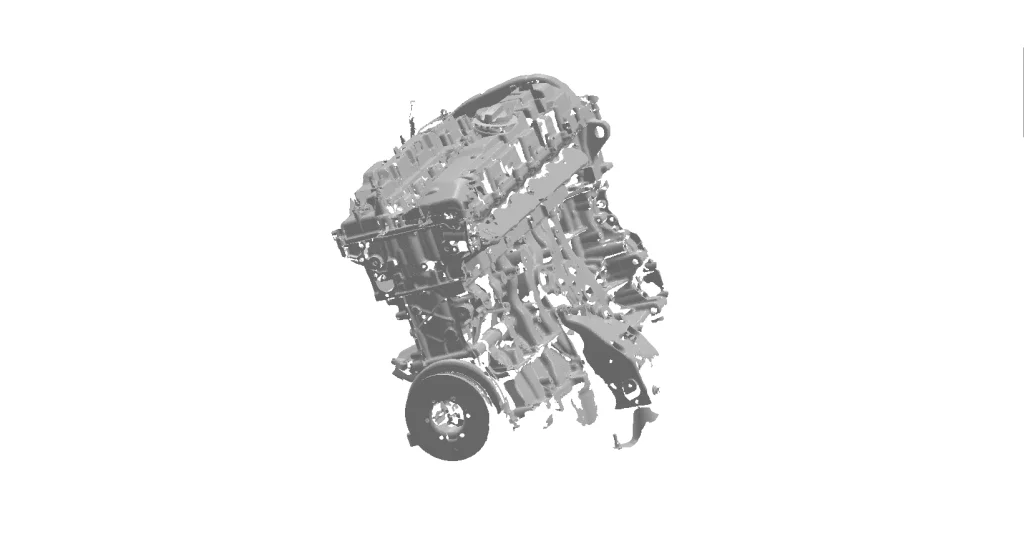
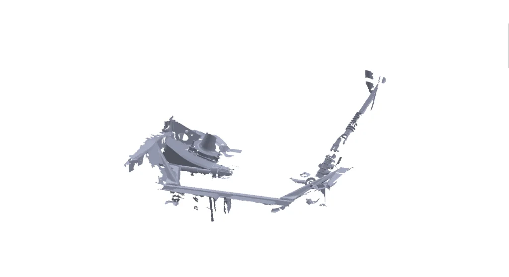
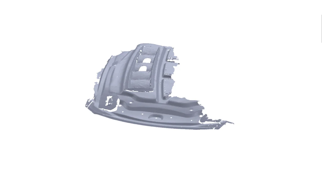
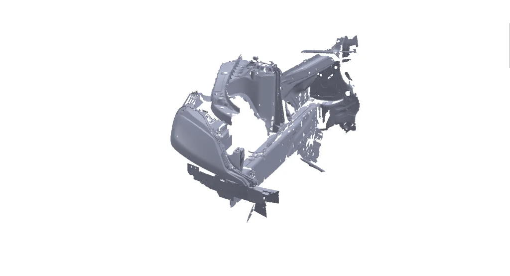
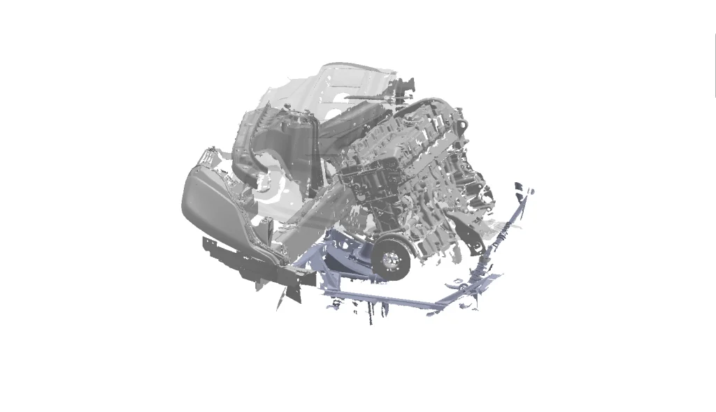
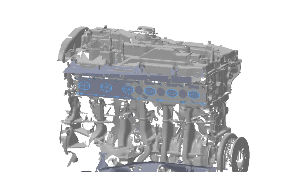
Before the design process could begin we needed to bring the Supra’s engine bay and B58 engine into the SolidWorks digital world. As previously mentioned, the design was being carried out remotely and with covid lockdowns in place we were unable to bring our Creaform HandySCAN SILVER to Papadakis Racing (for more information on our Creaform scanning setup and how we use it stay tuned for future blog posts). So Stephan had the scans done locally and emailed us once complete. The data included scan meshes, as well as iges files with sketch and surface geometry from the CMM probe arm. The meshes were imported into SolidWorks Part files as Graphic Bodies to define the design envelope in a visually clean and light weight (for the computer) setup. Below are screenshots of the engine as well as part of the front subframe, chassis leg/engine bay, and the underside of the carbon fiber hood.
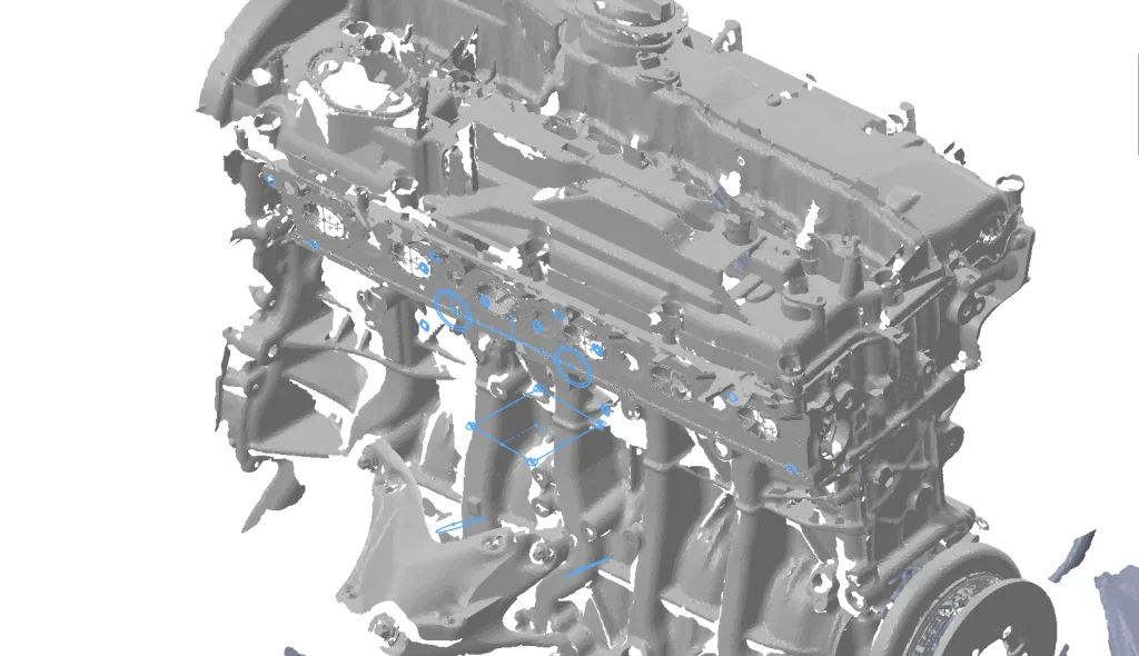
Once a unique part file was created for each portion of the reference geometry, the part files were combined into an assembly.
The CMM probe data was overlaid to create a datum point to base the new manifold design around. It was already decided that the turbo location should remain the same as the Full-Race production manifold linked earlier in the story, so its turbo manifold dimensional data was digitized and included for reference.
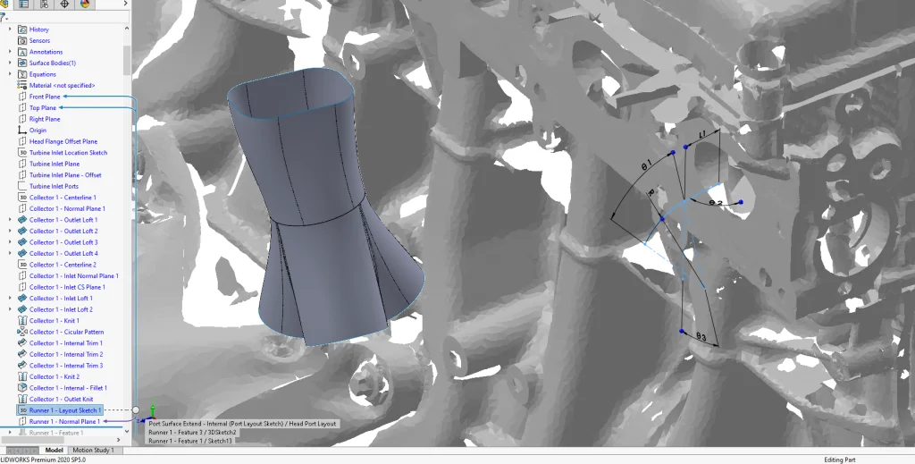
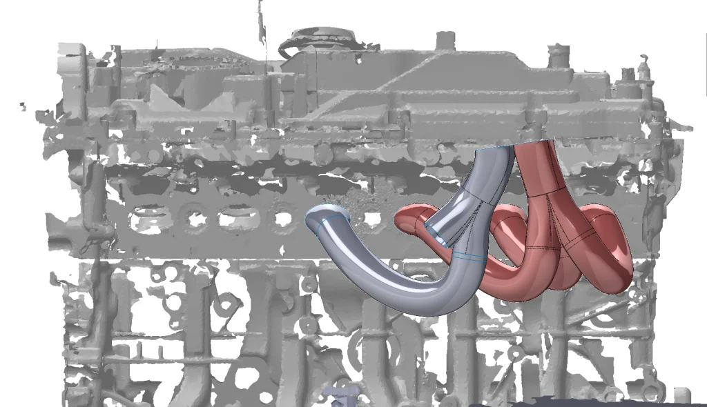
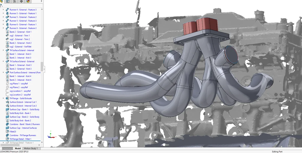
With all of the reference material assembled design of the new manifold could begin. In a new part file 3D Sketches and Planes were used to locate the turbine flange coincident with the probe data.
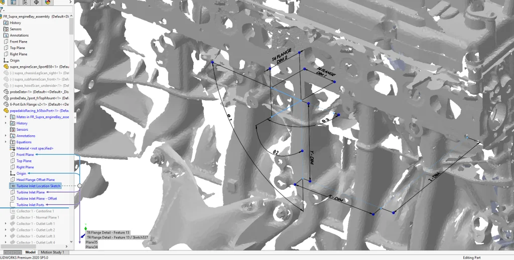
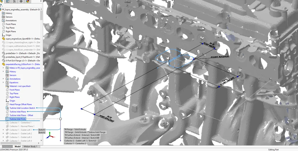
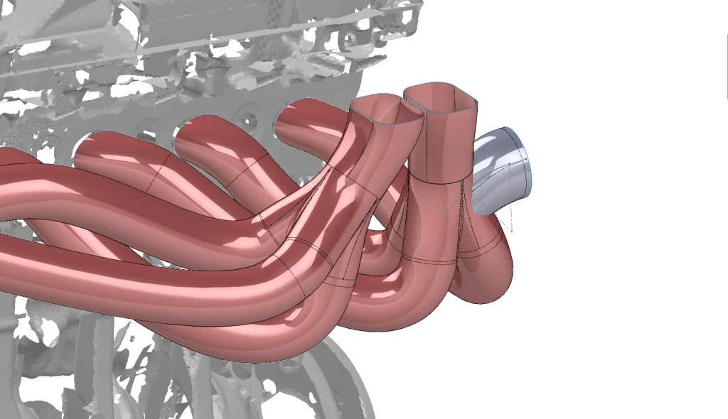
Then a 3D Sketch laid out the centerline for the cylinder 1-3 collector. The collector area where the three runners merge has a circular shape and the T4 flange layout for the turbine has rectangular ports, therefore a series of boundary surfaces were used to create the transitions from round runner to round collector, and round collector to rectangular flange.
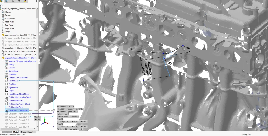
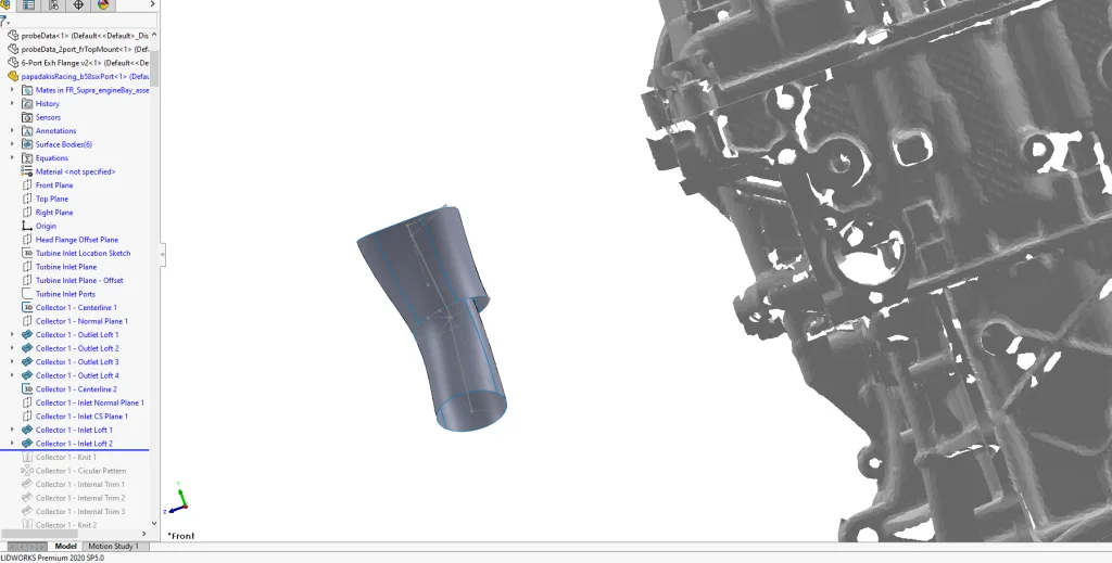
Surface Trims, Fillets and Knits were used to create the shape of the first collector. The approach used was to design the internal ‘flow’ surfaces, then external surfaces/solids, finally the internal volume was cut out of the solid.
With the cylinder 1-3 collector complete, the cylinder 1, 2, 3 runners were designed using Surface Lofts, Extrudes and Sweeps. The port transitions used a 3D Sketch with Arcs and Line Segments.
Because of the 3D Metal Printing process we weren’t restricted to any set runner shape so fully defined Style Splines were used to define their centerline path. An attempt was made to make the exhaust path as smooth as possible while avoiding tight bends.
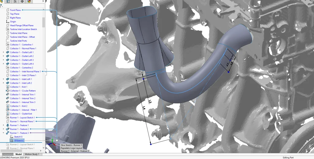
It’s important to note that when using Lofts, Boundary Surfaces, and Splines to take the extra time to ensure surfaces are smooth and free from wrinkles and strange artifacts. This attention to detail will improve the quality of the results.
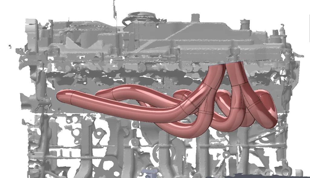
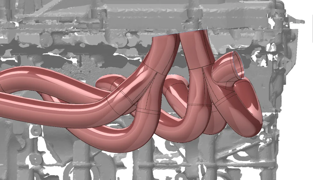
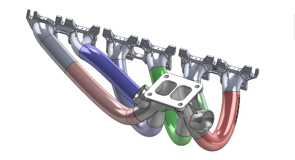
The same process was repeated for runners two and three, then the surfaces were all Knit together. Many people may be curious about the runner lengths and why they are not all equal. In short it wouldn’t be practical for metal additive manufacturing. Equal length runners would have driven the part count, and thus printing complexity through the roof when we were confident that direct, low pressure drop runners would provide the power needed. However, if you’re interested in monitoring the runner length for your project, the centerline sketches can be measured to give that information.
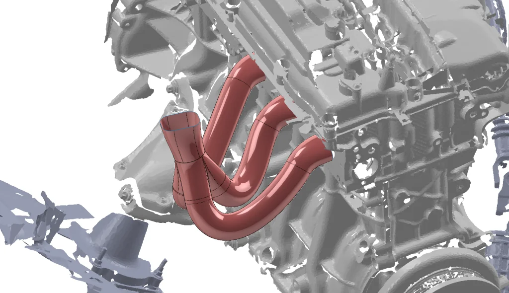
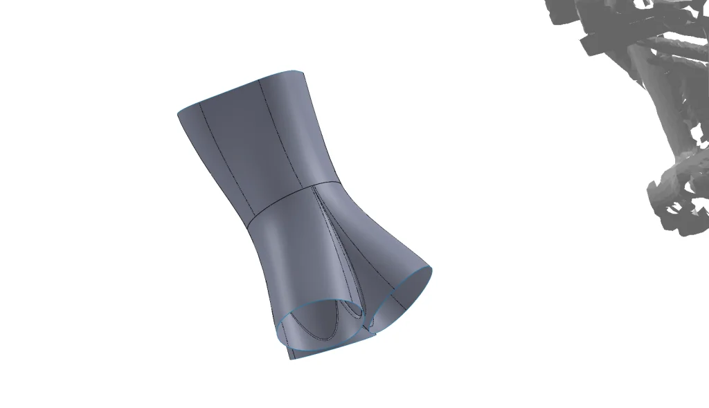
With the Bank 1 internal surfaces completed they can be viewed, as above, with RealView Graphics where it can be seen to be smooth and free of wrinkles or kinked surfaces.
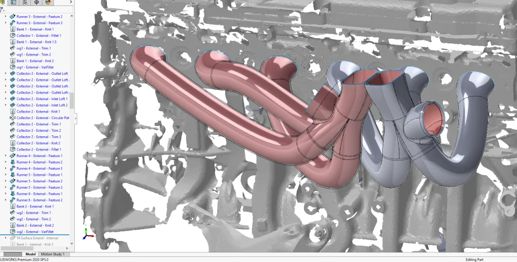
The above steps are repeated for the Bank 2 (cylinders 4-6) collector and runner layout.
Keep in mind the collector and runner layout wasn’t determined on the first try as the above process may lead you to believe, there were hundreds of adjustments made while finding a runner and collector layout that worked for all six cylinders. Of course the design was also checked for interference with the rest of the scans.
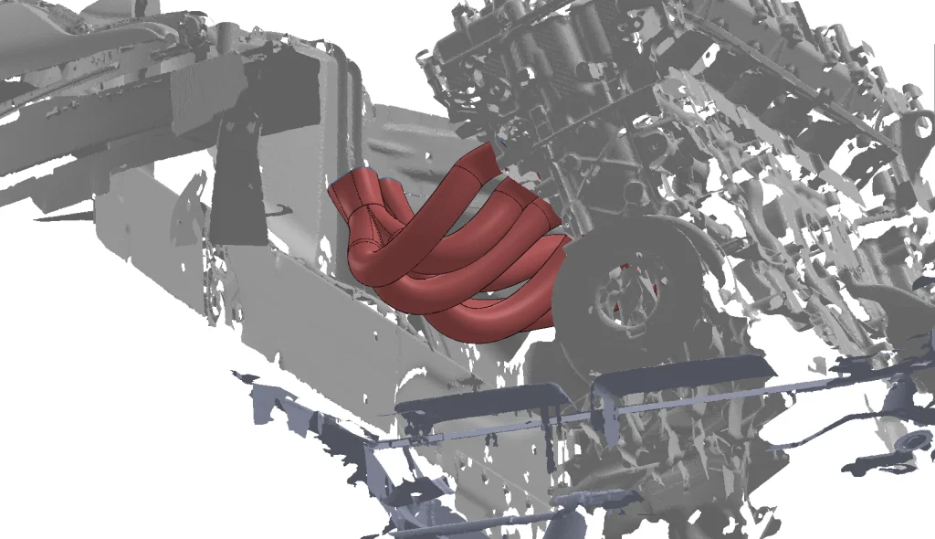
At this point the CAD models for the TiAL Sport MV-R wastegates were added in to help determine a suitable location for them, which would’ve also required a few more refinements to the collector and runner designs. The following shot also shows the BorgWarner EFR turbine housing. Keep in mind that if you don’t have access to supplier CAD and 3D scans, a lot can be done with simple measuring tools and patience.
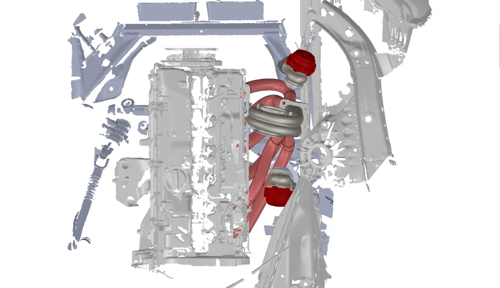
With the tentative wastegate location selected the wastegate tube design was started. This was done using very similar techniques to the collectors.
Special attention was paid to making a smooth, large radius transition on the inside of the ‘bend.’ This is done to ensure accurate boost control and eliminate boost-creep.
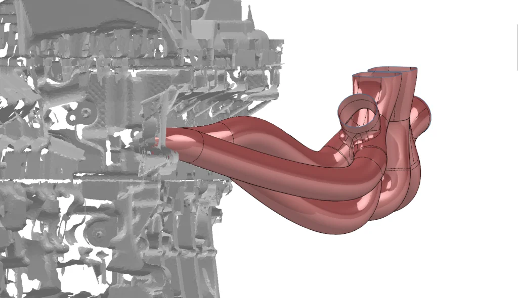
The collector, runner, and wasegate tube design process was repeated, this time for the external solid body. There were many ways to approach this, and sometimes experimentation is needed to figure out what approach works best. In this case the centerline 3D Sketches were reused, with new profile sketches offset by the desired wall thickness.
The external features were capped and Knit with the ‘Create Solid’ option checked. The flanges are modelled using basic solid Extrude and Cut commands and the bodies are combined.
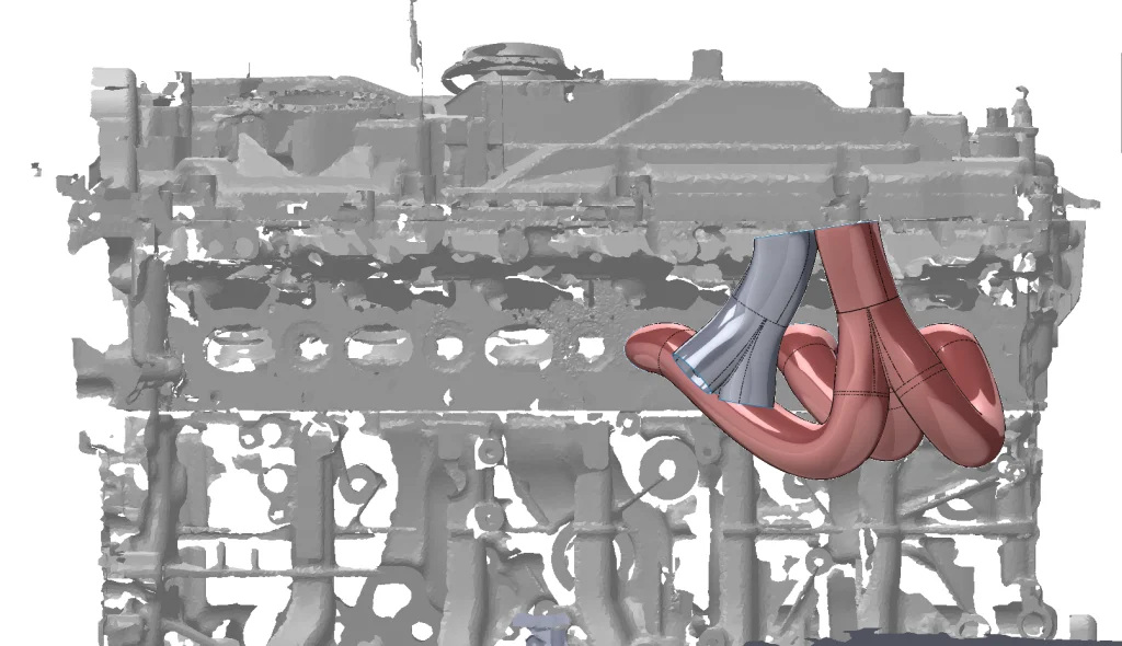
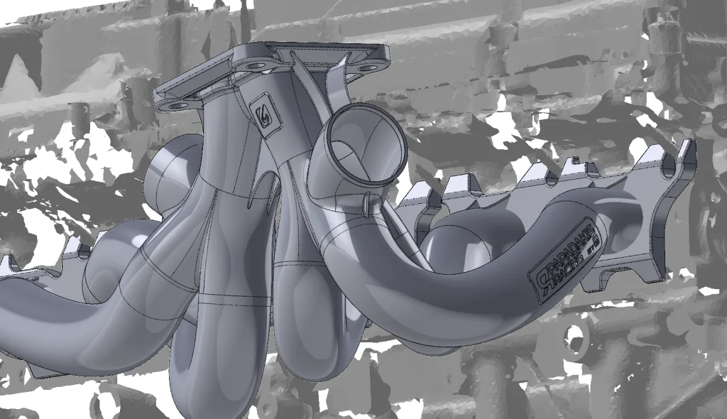
At this point the basic design of the manifold was complete but many many more features were added for a variety of reasons. Anywhere that there was enough space material was removed. Metal printing is largely priced by weight, so anywhere excess material can be removed, money can be saved. Some supports were built in to help support high stress areas of the part, Full-Race and Papadakis Racing logos were also added along with some features for cool looks. At this point the internal surfaces were cut from the main solid body, resulting in the one piece manifold below.
The one piece manifold above was far larger than what could be printed in one piece, also any area on the part with an angle shallower than 45° from the build plate requires support material. Because of this the manifold had to be sectioned into pieces that would fit the printer build volume and prevent supports from being built inside the collectors or runners. The support material is laser welded to the part and can be difficult to remove, if support occurs inside a runner it can’t be removed at all, therefore the sectioning up of the design was a subject of much discussion amongst those collaborating on the project. The more these printing principles can be kept in mind during the design phase, the more likely headaches will be reduced when it comes time to print.
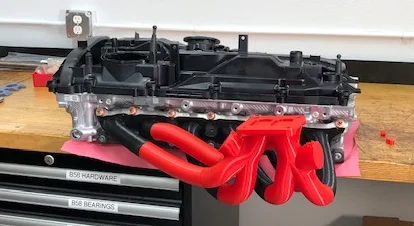
With the part sectioned into ten portions that could be welded together post printing, the solids were exported. A slight variation was also made to the design that allowed it to be easily printed in plastic to verify the fit.
End of AM Design Process
With the final design for additive manufacturing complete and the printer(s) at Mimo Tecknik working furiously, we had come down to the wire and didn’t know if the Inconel manifold would be printed and welded together (let alone tested) in time to make it to Round 7 of the FD season. The call was made to start on a Plan B turbo manifold – Fully CAD designed in SOLIDWORKS using the same 3D scanning, design, and plastic prototype printing technology used for the printed Inconel manifold. This manifold would be built in the traditional hand fabricated / robotic TIG welded style that Full-Race is known for. The design of the hand fabricated manifold will be covered in Part 2 of this blog post. Also, be sure to watch the “Turbo System Design – 3 Mistakes the Aftermarket Industry Makes” webinar to learn more.