

When coming to product design using SolidWorks software, surface modelling tools could benefit users creating different shapes and geometry with ease. Below are some of the options that you might not have checked upon:
1. Close loft
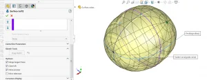
Loft surface is one of the most commonly used surface feature, which allow you to create geometry by joining selected profiles. In the property manager, the close loft option allows you to join the last profile back to the first selected profile, creating an all-round surface body as you wish:

2. Sketch point as profile
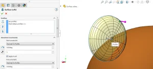
Another interesting skill is that a single sketch point could act as a profile when using loft or boundary feature. You could even apply end condition to control the surface. You could also apply this for the loft boss/base feature as well.
3. Shell feature failed. WHY?
After doing all the hard work creating surfaces, knitting them together and form a solid body. At this point you remember you need to shell the solid and feel anxious as the bad memory flashed back in your mind? Viewer discretion is advised.
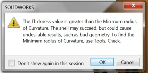
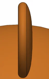
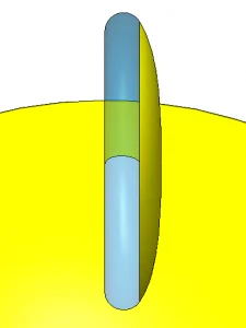
To help you overcome this nightmare, you need to first understand what is causing this error message. You could see that the thickness value of the shell is greater than the minimum radius of the curvature. In simple words, the wall of shell is thicker than the gaps between the surfaces. Seeing this message does not means that the shell could not be performed, but as a warning which the hollowed face might not be neat so you need to double check the internal region.

What if your luck run out and the shell operation totally failed to complete? One of the most common reasons is due to the zero thickness geometry. This infamous problem could be also found in drawing section view or combine feature, where your dimension entered matches the thickness/location of existing face. In this case SolidWorks could not determine whether the face should exist or not, hence causing the rebuild problem. There is not really an option or feature to get rid of this but to slightly change the dimension or existing geometry to avoid this problem.
For example, for a 3mm thickness geometry cannot use a 1.5mm shell thickness. An internal region of 0mm of thickness will be formed but there is no representation of this. Hence SolidWorks could not handle this situation and error is resulted.
There is not ready a feature or option specify for this, you as user need to determinate which geometry and dimension to be changed to avoid this condition.
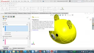
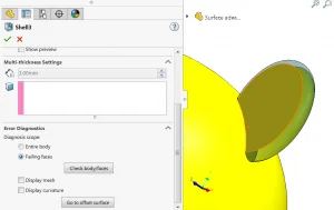
You would be able to see the failing faces appeared as a difference color when your shell failed:
Written by Jason Tse, Intelligent CAD/CAM Technology Ltd.