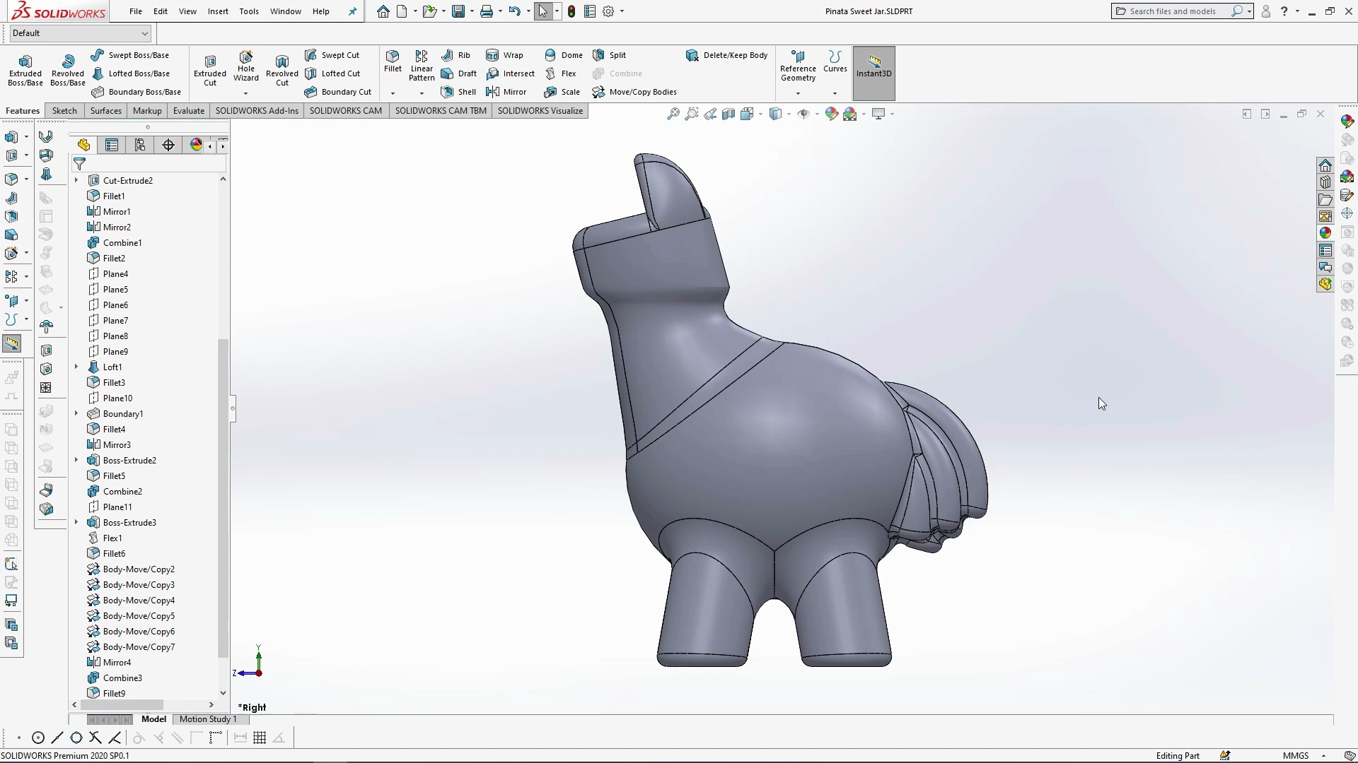
Pinata Sweet Jar – Part 1 – Tutorial
In part 1 of this 2-part SOLIDWORKS Tutorial you will learn how to create the body of a Pinata. This involves the use of DXF files, lofts with guides, boundary boss, move/copy bodies and the combine tool. Part 2 of the tutorial involves shelling the model to turn it into a 2-part jar, and applying decals. The DXF file used in this tutorial is available to download here.. By the end of part 1 of the tutorial you will have the main body of the Pinata created ready for part 2.

The neck of the Pinata is created using a guide DXF file which shows you where to add planes to create loft profiles, but also acts as guide curves for the lofting feature. The guides were created in a vector based programe, exported as a DXF and imported into SOLIDWORKS. If you draw a dashed line in the vector software, they will come in as a center-line guide sketch. Six new planes were added along the DXF sketch centre-lines, these were used to draw the lofting profiles.

The outer sketch curves were used as guide curves with the loft. Guide curves can be very useful in achieving the exact profile from your loft profiles.

Boundary boss was used to create the Pinatas ears, and again a guide curve was used created with a 3D sketch to inform the boundary on what path to follow joining the two faces. The boundary boss can be very useful joining up two touching sketch profiles along a guide.

The Pinata tail was created using a flexed boss extruded body, it was copied and moved into place, Several copies were made, and mirrored mid plane so that the tail was symmetric. Move/Copy Bodies allows you to copy, move and rotate or even mate bodies into place, it is very precise, and gives you full control of the placement of multiple bodies.

The tail copies were combined to the Pinata body to become one body, all edges and joins were filleted. With the Pinata complete, watch Part 2 to see how the jar is shelled, the lid fixture is formed, and decals are applied.


