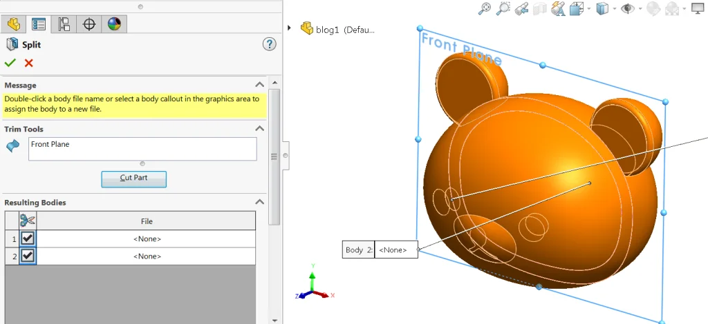

Continue from our last model, now it is time to divide the shelled model into two pieces using split feature and a plane:
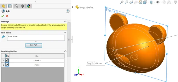
(Note that split feature [insert > feature > split] cuts a solid body into pieces based on the entities selected; while split line feature [insert > curve > split line] only divide model faces into smaller pieces using sketch or intersection of other geometry. These are two different features)
The split feature also works with surface and sketches:
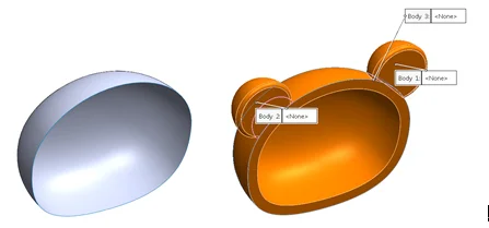
You could even save the cut bodies into new part files by assigning names to them. But normally it would be the final step of your modeling, not with an unfinished design.
For the next part we will try to the two solid bodies to align easily in real life, by using the fastening feature – lip/groove:
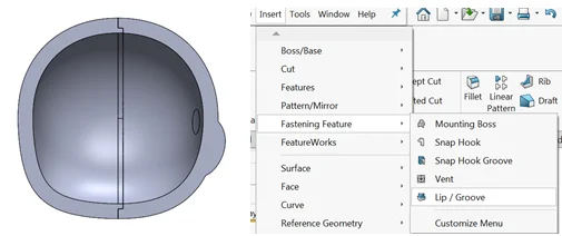
By selecting the groove face and edges, pairing with the lip face and edges, you could easeily obtain the new geometry following the parameters you have entered.
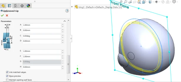
It works very similarly to sweep and sweep cut, but by using fastening feature:
- You do not need to create profile sketches for sweep
- You can control the parameter of both sides in a single feature
- Gaps and draft setting could be easily achieved and changed
- Setting could be saved and reused even in other files
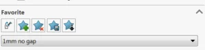
However, if you want to create a customized profile for the lib and groove, you would need to use the sweep feature instead.
The next fastening feature that would be helpful is mounting boss.
To begin with, mounting feature allows you to create two types of fastening method: pin or hardware:
Pin fastener type
Hardware fastener type
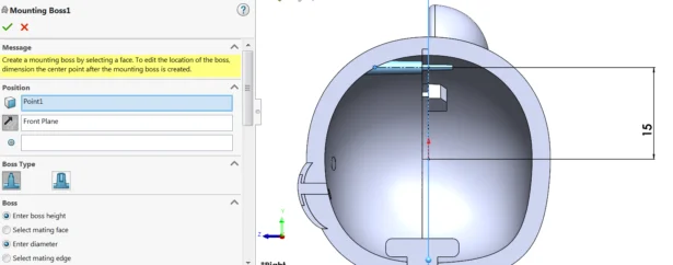
To create this feature, again you would not need to use sketch to draw the profile, but simply select a point where you would like to build the pin, and a plane for the pin’s direction:
Similar as before, you would have a table to fill in the diameter controls:
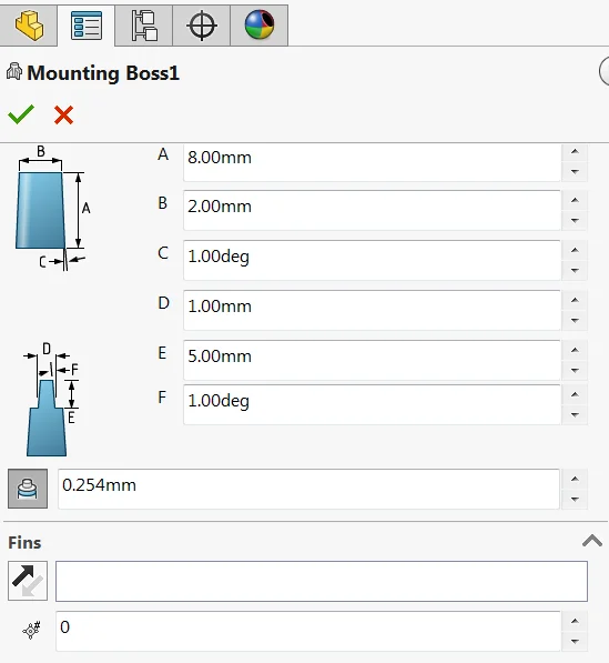
And you could save the setting for later use.
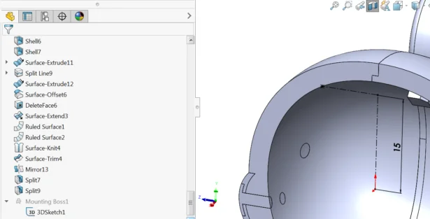
For the positioning, you would edit the 3D sketch to add dimension or relation on the sketch point for a more precise control
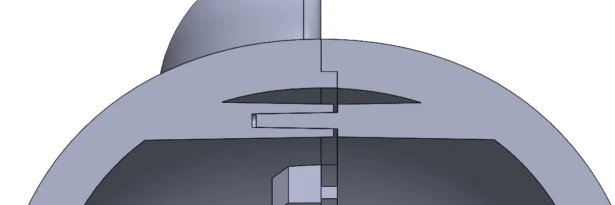
To create another half of the pair, again select the point and direction, but this time also select the circular edge of the pin for positioning:
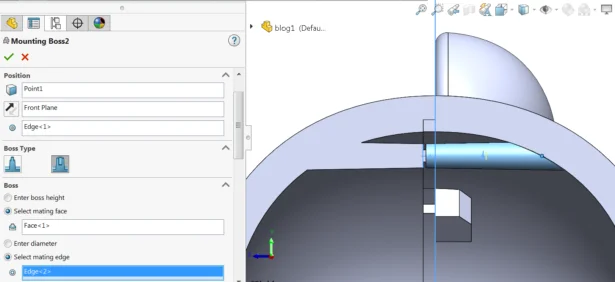
For the parameter, simply select the mating face (touching face of the pins) and the mating edge (at the tip of the pin), a matching thread pin would then be created.
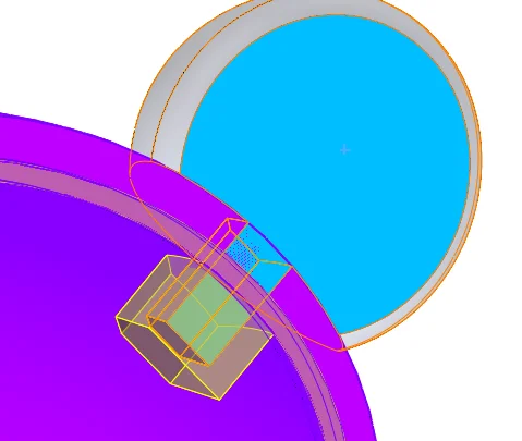
If you find overlapping solid bodies, you could also use indent to cut one body based on another:
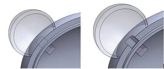
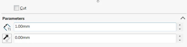
Remember to check the “cut” checkbox to create a simple cut, while keeping both bodies
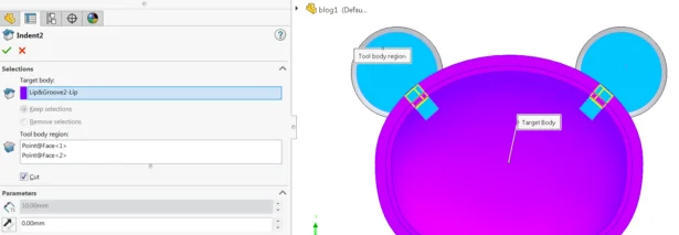
Or you could leave the cut checkbox cleared to create a “pocket” with the thickness input:
In the next blog we would finish the model by tidying up the part file, like removing unwanted faces or bodies, to prepare for export to an assembly file. Stand tune if you are interested in learning more tips and tricks in SolidWorks modelling.
Written by Jason Tse, Intelligent CAD/CAM Technology Ltd.