
Applying the correct boundary condition in FEA Analysis it’s imperative, otherwise the risk is to get useless results because the setup was faulty. Using the correct tool so It’s very important when you have in mind what to apply and you want the most realistic behavior from your analysis.

In this article I will explore the use of Coupling connector that helped me define the best setup in many cases and not only. It is also very important to get the results you want in the easiest way.
The Coupling connector is not really unique to Structural Professional Engineer but I’ll show you that is going far beyond the “standard” use in other packages. In SOLIDWORKS Simulation for example we can use similarly the remote load/mass connector for imposing special boundary conditions but it hasn’t all the plus of the Coupling connector. Take a look here for more information.
With it we can:
- Setup a single point of application for Loads (Force and displacements) and Restraints
- We can connect single or multiple surfaces to a virtual “center of geometry” point.
- We can connect couples of multiple surfaces with a direct or averaged connection
- We can define a single sensor for Force-Displacement plots
Let’s view now the simplest way to use it.
I will take as an example this rubber part that I want to analyze in compression. To setup the coupling connector we can just click on the top surface and leave the default type “continuum distributing”.
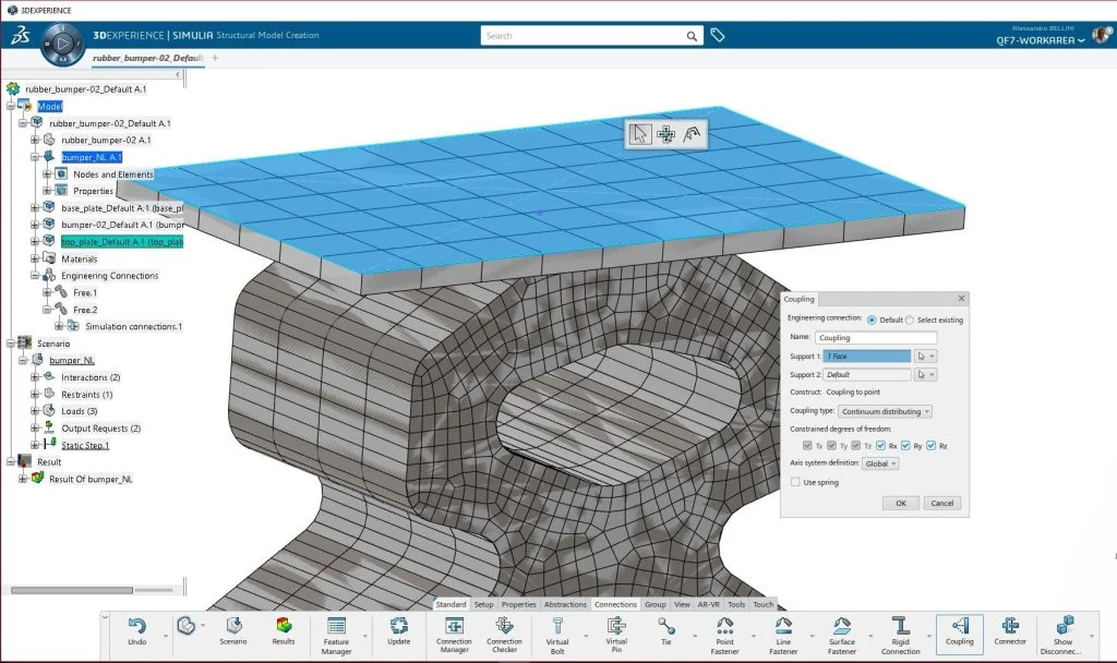
It will create a single point at the center of the surface coupling the motion of the face to the motion of the reference point. The coupling is averaged with weight factors controlling the transmission of forces from the reference point to the support.
A continuum distributing coupling couples the translation and rotation of the reference point to the average translation of the coupling nodes. No moments are distributed at the coupling nodes.
Optionally we can also input spring constant for the connection.
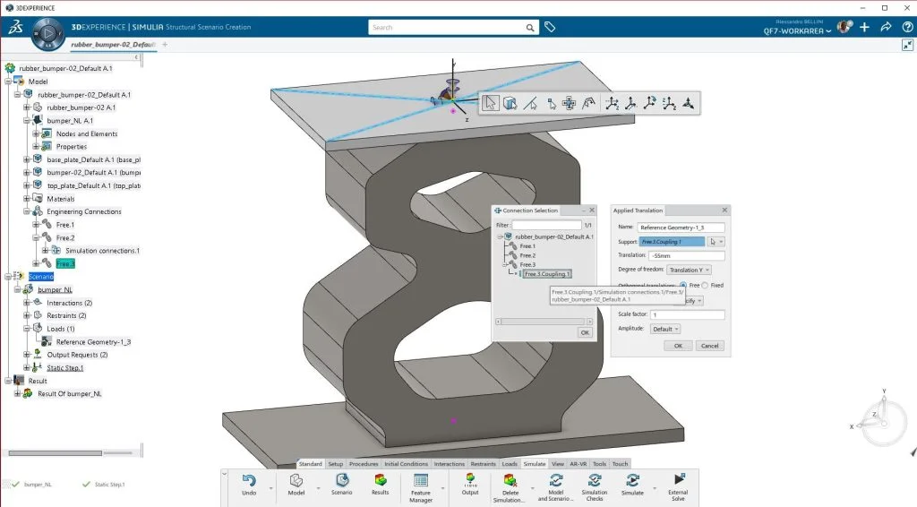
Once it’s done, I can use it for define restraints and load. Very easily I can just click on the right arrow icon and select connection and I can select the coupling from the list.
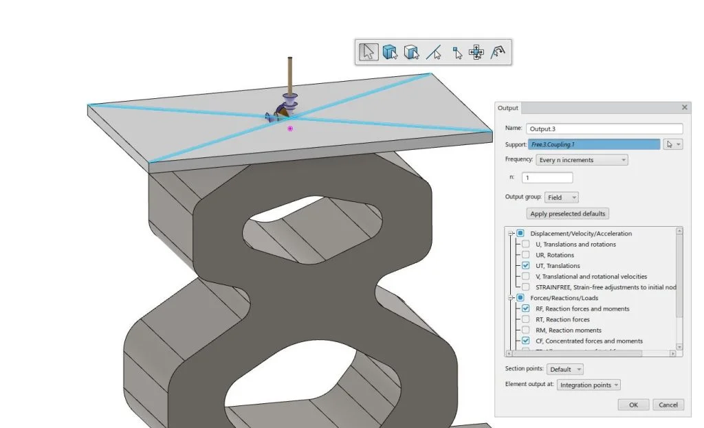
Now I can define a sensor for the Forces and Displacement over the coupling point. This will help me create a plot later with ease. I go to the Simulate Tab of Structural Scenario and click on Output.
Here I can again select the coupling and all the results I want related to it (Forces and Displacements in this case).
Reaction Forces will have a value in case you are applying a displacement, Concentrated Forces if you have a Force on the coupling connector.
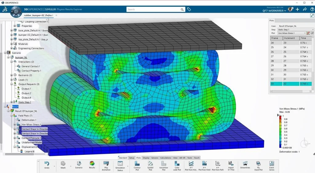
Finally when you have results loaded you can define a Force-Displacement plot from the Coupling connector.
To do so click on X-Y Plot from history and choose Reaction Forces and the component you want to plot in Y Axis, then instead of time choose a variable for X-axis and select the displacement component.
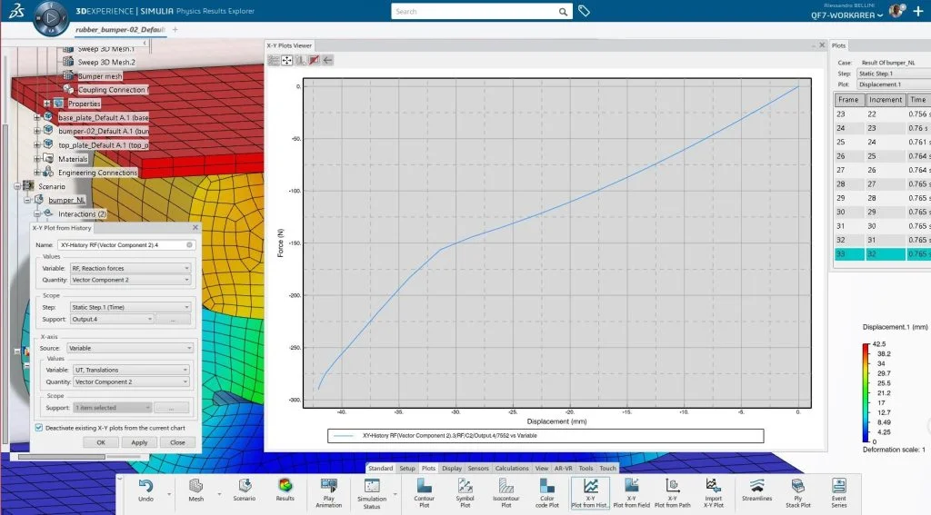
You will get a plot like this in the picture where you can analyze the behavior of the coupling connector.
Hope this helps, enjoy your analysis with Structural Professional Engineer.