

When you are dealing with a Non-Linear Analysis inside SOLIDWORKS Simulation Premium sometimes is really hard to get the job done. Here there is an extract from my presentation at SWW Los Angeles in 2017 to enhance your workflow and have a smoother experience with Non-Linear module.
First some advice about the use of the module: don’t go immediately with it but start with a Linear Static Analysis. Later on, when you are ok with the setup, you can convert easily the linear study in a Non-linear one.
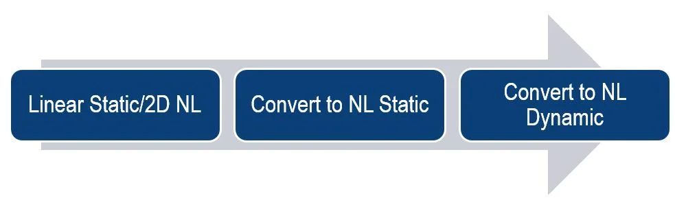
In addition, if you find it unstable you can again convert it in a Non-linear study and try to use the damping as a “stabilizer” for the run (check also my presentation at SWW 2018 about Rayleigh damping here: https://www.youtube.com/watch?v=i6NcZuBUOFE.
This approach has many benefits:
- It’s quick to run to check contacts and boundary conditions
- The mesh can be transferred once you find the good balance between precision and speed
- Linear material model will give you an idea what to expect.
Speaking about meshing, start always with a draft mesh to save time. Once you identified a good mesh, you can easily switch to the second order.
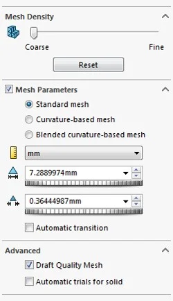
Also Standard mesher should be preferable in the first place because it has more predictable behavior and you won’t get additional nodes that you don’t need. If the standard mesher is not good for your model switch to curvature-based.
It’s a good practice to use the split command over geometry hard to mesh. Use it for helping the mesher to start with edges you decide, in addition it’s a good tool to have results exactly where you need.
Now let’s talk about contacts, the most difficult part to manage in a Non-linear analysis. Some hints about contacts:
- Start always with Global bonded contact and then apply no-penetration contact sets.
- Try to have to the same mesh element dimension across the region in the contact set
- Use a mesh control to have a uniform mesh over a highly deformable component (like rubber sealing)
- Choose source and target selection (in the contact set window) thinking about a bullet that is smashing into a wall. The source will be always the selection with more complex surfaces and/or smaller than the target. The target usually is selected over much smoother surfaces.
- Don’t use many contact sets with fewer selected surfaces but try to group them in relation to the contact region you imagine will occur.
- Always use surface-to-surface contact option in the no-penetration contact sets
- Use friction only when necessary and only in a specific contact set (it slows down the calculation)
- Use 0.05 friction in problematic contact set to avoid sliding and so stabilizing the run.
The last part of this article is about solver settings. Usually the default settings are fine but with complex models, involving many contact sets, hyperelastic materials or load-unload boundary conditions, it’s better to change them. Let’s review them:
- Use always Direct Sparse or Intel Sparse (make sure to have a lot of RAM)
- FFE+ or other solvers should be used only if you are running out of core (not enough RAM)
- Set convergence tolerance to 1e-06. It will slow down the run but it’s more probable to finish it. Better to wait more but to have results to watch.
- Set maximum equilibrium iterations to 50 to help in difficult step calculation.
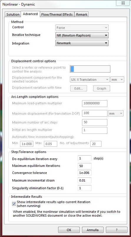
In addition, it’s very important to setup a good time step in the solver window. There are few tips here based on experience. Try to imagine the time step as the speed and acceleration you want to drive your car. If you use a slow speed and low acceleration, you can easily drive everywhere but you will waste a lot of time. Instead, if you use too much acceleration before a curve you can have troubles.
The minimum time step is exactly the minimum speed you want to set for the analysis, this is extremely important but the default is fine for almost every run. Then you have to set a maximum time step, this is again in terms of velocity the maximum speed you allow to drive your run. If it’s too high the risk is to receive an error from the solver that has stopped due to convergence problem. Usually I try it a 1/10 or a 1/20 of the total time set for the analysis. Last value to set is the initial time step, this is the initial speed you take to start your drive. If you know there is some complex contact at the beginning of the simulation you can cut it in half from the maximum time step but usually I set it at the same value.
Hope to be of help, enjoy your Non-linear analysis!