

Finding a replacement part can often be a hassle, even for the simplest of products. Calling up customer service and trying to decipher exactly what widget you are attempting to order can be next to impossible without having the unique SKU or Part Number needed. Seriously, who has that on hand?! Luckily, SOLIDWORKS Composer has an easy way to generate interactive 2D web content that can help probe into assemblies to perfectly identify these parts (check out these examples). This blog post will walk you through the four steps to create these interactive images from your CAD data.
The process of creating Interactive content really comes down to 4 simple steps:
- Create Views
- Create Links
- Export Images as SVG
- Embed to HTML
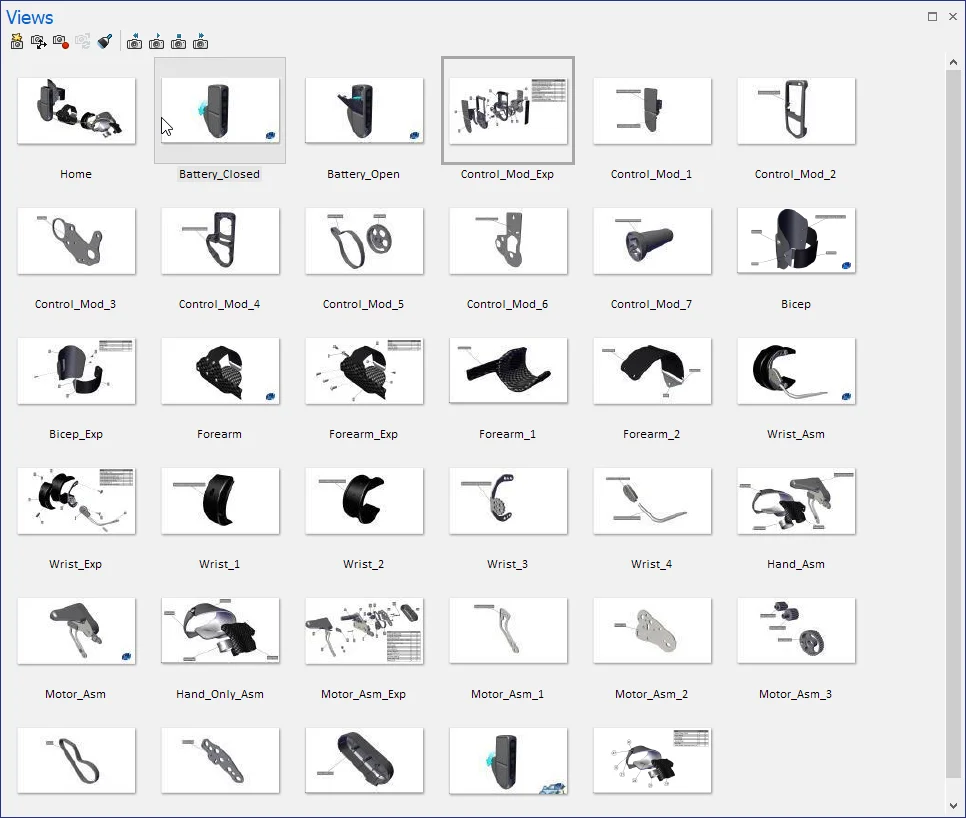
STEP ONE: CREATE VIEWS
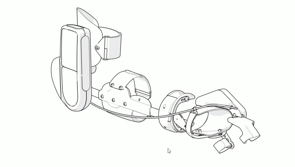
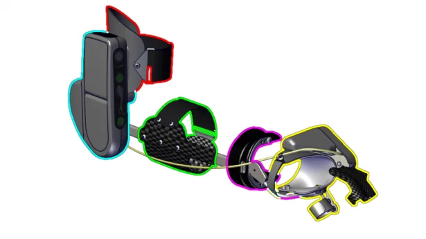
Let’s take a look of these for steps a little closer starting with capturing your interactive images in SOLIDWORKS Composer. Hot spots can be really handy for selecting sub-assemblies from the top level assembly that will be the starting point. Determine how you plan to break up your assemblies to easily navigate. Each hotspot can have its own unique color by locating the hotspot and overriding the default color option. I also recommend renaming these hotspots to be descriptive of the sub-assembly, these callouts are visible on the tooltip when hovering over.
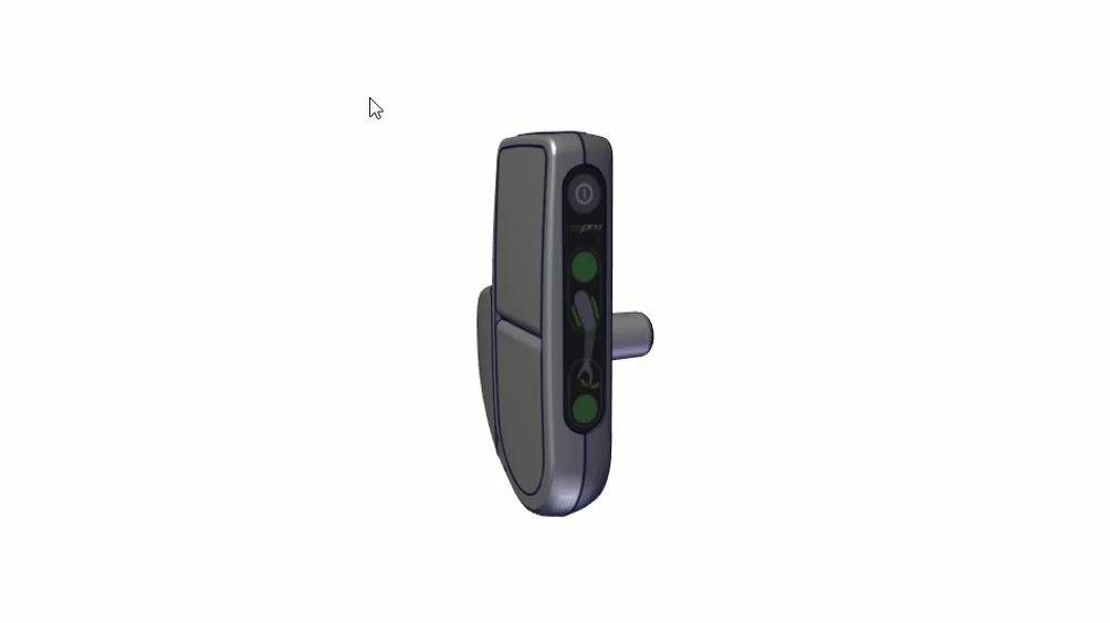
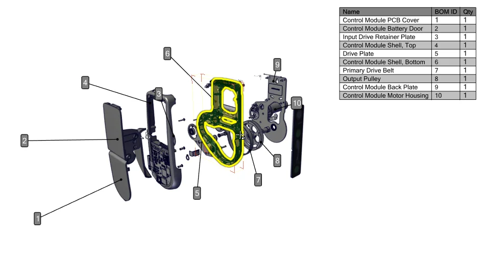
I selected the battery pack from this assembly and create another view (the links to connect the views will be added in the second step so you don’t have to worry about that right now). Using the transform tools, it’s easy to create an exploded view. Often with more simplified sub-assemblies this will be enough to address finding the appropriate part, especially with an interactive Bill of Materials created. It’s a simple process so might as well attach one to each exploded view you create.
Creating a BOM from an Exploded View
- Create a BOM from selections
- You will need to window select the exploded items to include
- Generate BOM ID’s
- Create Balloons
- Show/Hide BOM Table
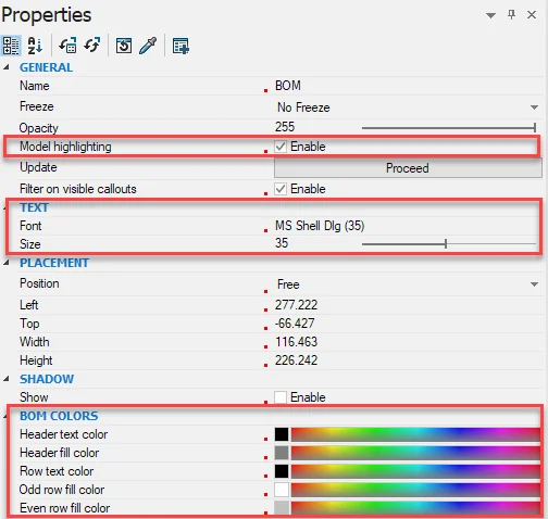
Of course, these all have custom properties worth playing around to give a nice final look, so spend some time familiarizing yourself with these. ALWAYS enable BOM highlighting to get the feedback between the exploded view and the actual table. I generally size up the text, change the style to parametric and add some shading to the table itself, but really it comes down to user preference.
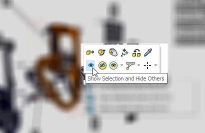
Generate Single Part Views Quickly
It’s a pretty quick process to build views for each individual part from the exploded views you have created. Start by right clicking on a part from the sub assembly exploded view and selecting the ‘Show Selection and Hide Others’ will get you there in one step. Then just snapshot the view and move back to the explode view to repeat this process. Really what we are trying to accomplish in this first step is taking a snapshot of each sub-assembly and then each part if you want to provide that much depth to your end user. Some instances, the interactive BOM is enough, in others you may want to go the extra step down to the single part.
Add Web Buttons
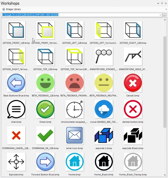
This is also a good opportunity to add any supporting images to the views that you are capturing.
Pro tip: Grab common icons to compliment what Composer comes with in the installation. Home, back, forward, different views, anything that might add to the navigation can all be done in 2D image format and added to your image library from the Workshops.
STEP TWO: Create Links
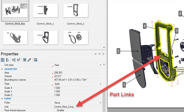
This gets us to the second step, creating the links. Links can be created FROM just about anything TO just about anything. For this type of content, a link from our defined hotspots for assemblies and parts for exploded views to the appropriate view is all we need. So essentially, drilling down from the top level, to sub assemblies, to exploded views to finally the final part.
Now here is the secret sauce: instead of linking to the VIEW itself, you will link it to SVG file that will be created from that view. For example, from the main menu I will create a link from the battery pack hotspot to the ‘battery_pack.svg.’ We will be creating these files in the next step when exporting the svg files themselves. These links get created inside of the SVG files when the vector image files are created. Once loaded online or tested locally (I recommend Chrome), everything should work seamless as long as they are in the same root directory.
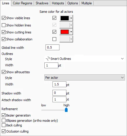
Now that you have created your links and updated all the views, it’s time to start saving the SVG files. I like to do a series of test images to make sure the final images will look good. Under the workshops in technical illustrations you can refine line weights, add/remove color and change the outline styles and test the final svg image through the preview button. Here are the settings that I generally use for black and white SVG output:
STEP THREE: Export Images as SVG
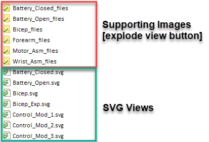
Next is step three, exporting the SVG files to a common directory. I use a ‘_svg’ subfolder in the same location that the HTML files are being saved. This makes it easy to reference the ‘main menu’ SVG file that will then reference all the subsequent svg files. When you are saving these images out, Composer will also create a series of sub folders in that same location to save out any supporting images (like the navigation icons I mentioned above). Keep these files in this directory as well. Each supporting 2D image get a new name and are referenced in the SVG file. You COULD create a single image instance if an image is used more than one, but would have to find and rename in the SVG and really isn’t worth the extra time to save a few kilobytes of space.
That’s it for the interactive content creation. At this point, you should be able to open your first image, in this case I named the first SVG that I want my end user to start with “Myomo Home.svg.” Since all the links created reference the additional SVG files, they will open the next image in the browser. Start testing and make sure all of you links are valid.
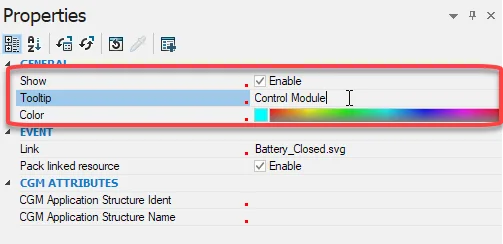
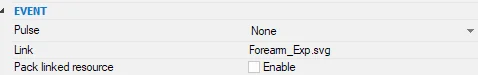
If you see that they are NOT working, check in Composer that the link is indeed pointing to the SVG file in the correct location, and I also uncheck the ‘Pack Linked Resource’ in the event properties to keep the SVG files separate. This makes updating files an easier process.
STEP FOUR: Embed to HTML
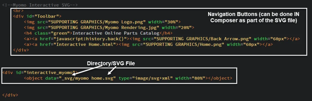
Now it’s just the last step, adding your HTML line of code to reference the SVG file and upload to the hosting service. Of course, a google search how to add an SVG link the HTML, but the basic line needed is just this (your syntax will be different):
The object data in this case is pointing to the sub folder in the directory where I saved all of my SVG files, hence the _svg/. Then just the name of the ‘main menu’ or ‘home’ svg you want the end user to start with “myomo_home.svg.” I added the width percentage, use a percent of the viewable page vs a pixel definition so the svg files will be responsive.
The process is really pretty simple once you run through it. Almost all of your time is in the capturing of images and creation of links. The HTML side is just one single line of code to bring in that first SVG file that will reference the rest. So with little effort and the help of SOLIDWORKS Composer you can build some really cool interactive online content (and not just limited to parts catalogs). Now go ahead and give it a try! To learn more on how SOLIDWORKS Composer can help streamline technical publications, like installation manuals, assembly instructions with easy to follow visuals, give your local reseller a call today.