SOLIDWORKS Routing
What is SOLIDWORKS Routing?
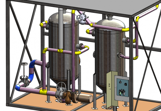
SOLIDWORKS Routing is an add-in that allows you to completely automate the process of routing pipework, tubing or even cabling, saving you many hours of modelling against traditional methods.
In this article we want to show you the benefits of using this package. We know that projects often have tight deadlines, so saving time at any stage can take some pressure off. SOLIDWORKS Routing is a package that is available with all Premium Licenses.
How does it work?
A Route path is driven from a 3D sketch, so what is the software doing in the background? SOLIDWORKS Routing is driven from a database. Once you have selected the correct schedule you are using, it will automatically pick up the relevant parts to that schedule. For example, if you use an edge flange ‘Sch40’, all the pipes and elbows will be the same schedule. It then assigns the relevant routing components to the 3D sketch.
Can I not just use tradition sketching methods to create piping?
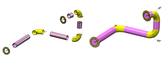
Your alternative method to create Pipework would involve using 3D sketches. You can then connect the relevant pipes with a series of sweeps and custom made flanges. Using this method, you will not get a bill of materials produced on your drawing. This can add a significant amount of time onto creating your models.
In SOLIDWORKS Routing, once you have completed your pipework, you will have the option to output the model into a 2D drawing along with a Bill of materials that will list the correct pipe information i.e. cut lengths of pipes. This option will not be available if you have created it manually. Another advantage is the ability to easily define Spool segments, and it will capture the correct detail when brought into a drawing.
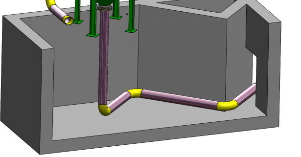
SOLIDWORKS routing has a fantastic ability to auto route between the given routing points, but if for example your route needs to follow a wall you have the option to route along geometry.
What makes up a routing component?
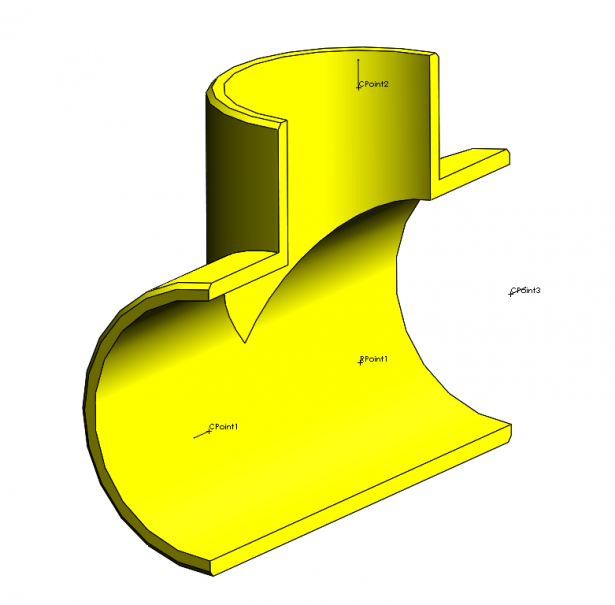
For a part to be considered a routing component, it needs to contain certain attributes (Route points and Connection points). These are easily added though the Routing Component wizard for custom parts and are already present in the Design library or any standards you may download through SOLIDWORKS content. Connect points (C-points) will connect the component to the 3D sketch, and Route Points (R-points) define the direction and position that your pipe tube or cable will start.
Importing P&ID
Engineering projects are rarely run by a single person. For example, if you are working on a plant layout, the Project manager will be able to feed back the locations of the equipment (via a .xml file) and SOLIDWORKS is then able to automatically route between the components.
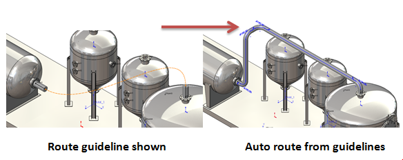
What’s the Difference between the Types of routes?
Piping is Rigid and often follows straight pipework with 90 or 45 Degree elbows to change directions.
Tubing you could imagine a rubber hose, which is controlled by a spline to get free form shapes and routes.
Cabling acts in the same manner as Tubing but is used for electrical.
Validation?
If you have previously created your pipe layouts in a 2D format, you have no way of finding out if your system will work correctly. Another advantage of using SOLIDWORKS Routing is that you’re able to run flow simulation on you routes.
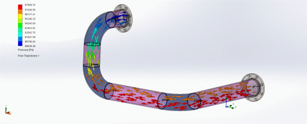
The image above is representing a Flow Simulation run on a basic pipe layout, and has been presented to show areas of high and low pressure, allowing you to modify and validate your piping routes.
If you would like to know more about SOLIDWORKS Routing, why not attend one of our training courses?


