

There’s no better way to end 2017 than with a SOLIDWORKS challenge! I’ve tasked myself to design a snowflake using all of the feature patterns available in SOLIDWORKS. Do you think I can do it?
The patterns I will use for this challenge include:
- Variable
- Curve Driven
- Mirror
- Linear
- Sketch Driven
- Circular
- Table Driven
- Fill
I consider Mirror to be a pattern; the results of using symmetry is a type of pattern. In this version of the challenge, I use each pattern once and only once. If you decide to take this challenge, you can change it so that patterns can be used more than once. Either way, it’s a fun challenge so don’t be afraid to give it a shot! Without further ado, here is my crack at the challenge.
1. Variable Pattern
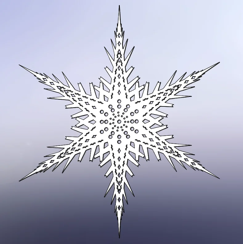
Let’s start off by using two boss extrudes to give the snowflake a nice shape.
For the first extrude, I create the tall spike from a line and an arc. For the second extrude, I make a small side spike in preparation for the first pattern. The idea is to pattern this along the curved side having the instances get smaller as the spikes go up. This is perfect for variable pattern, so let’s see how to set this up.
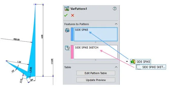
In the first box, it asks for the features to pattern. In this case, it’s just the side spike itself. The second box asks for a sketch or a piece of reference geometry to vary to create the pattern. We’ll be making modifications to the sketch itself, so the appropriate selection here is the sketch that defines the spike.
Once we have those in place, we can hit “Edit Pattern Table” to make some modifications.
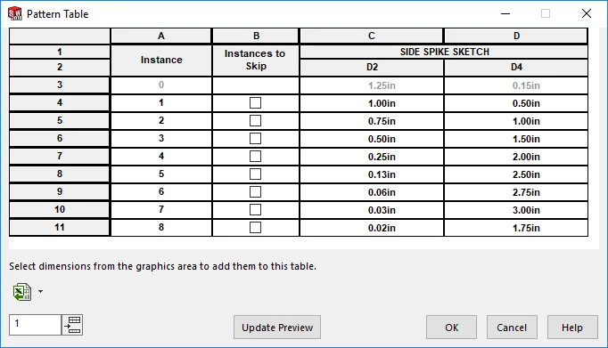
A window like this comes up. (Please note: If you’re setting this up for the first time there would be no dimensions.) Click dimensions in the graphics window to add them. At this point, click on each of the cells to change the value to whatever you want. I changed the offset from the bottom corner (D4) and the length of the spike (D2). You can also skip instances if you wish. Click “Update Preview” to see if you like what you see.
Hit OK, and we have our first pattern!

2. Curve Driven Pattern
Continuing, I cut extrude this “wing” shape near the curved side of the overall shape.

The plan is to pattern this all along the curved edge following the edge. For patterns that require following a path, Curve Driven Pattern is the way to go. However, we need an extra bit of information before we can launch the command. Curve Driven Patterns like to follow the curve exactly, right to the end points. In order to get that geometry, start a sketch, and use the “convert entities” command to create that arc. Drag the endpoints to resize the curve (remember the patterns go right to the endpoints). Now we’re ready to launch the command.
The first box is asking for the curve to follow, so select the converted curve. Set the number of instances and the spacing if required. I want to keep the instances equally distributed throughout the curve, so I check the “Equal Spacing” option. It looks like 6 is enough. Now for the curve method. If you consider what we’re after, we’re not following the curved edge, per se, but we are following the offset of that curved edge. So I will select the offset option. Not only do I want to place the instances along this curve, I want to orient the instances with respect to the curve. Selecting “Tangent to curve” will rotate the instances ever so slightly to match the curve. And don’t forget to pick the feature to pattern!
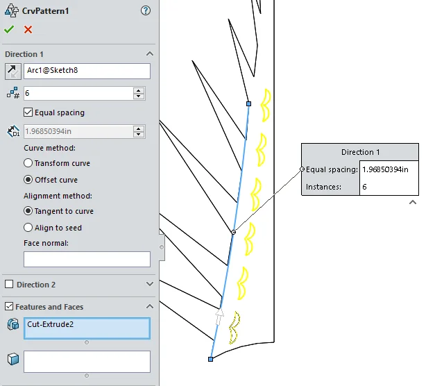
Hit OK. Now we have the result as seen below!

3. Mirror
This one is very easy to complete. I already have half of the part modeled, and now it’s time to get the other half done! I built the straight edge vertical to the origin, which means the right plane bisects the full spoke.
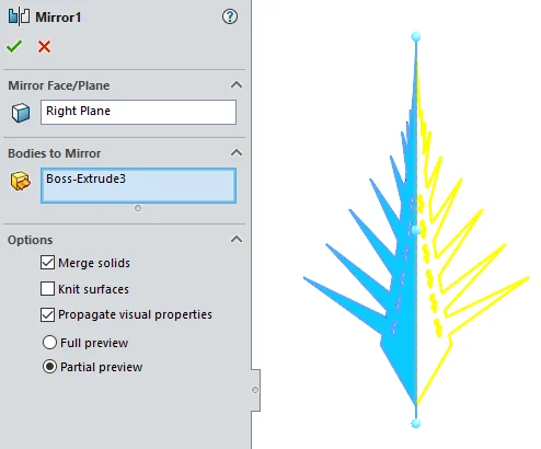
For this mirror, I select the right plane as the mirror plane and click in the Bodies to the Mirror option. We want to mirror all the geometry, rather than just some features, so body mirror is the ideal option. Remember to merge solids so that we have only one body. Shown below is the result.

.
4. Linear Pattern
Now that the spoke is mirrored, the center looks a little barren. Let’s fix that with a Linear Pattern! Most SOLIDWORKS users have linear pattern in their toolbox. It really is a powerful tool with the ability to skip instances, vary instances and go up to a reference. This Linear Pattern is set up simply. Eight instances separated 0.36 inches apart renders the geometry I want. Notice the direction I chose: it’s the top plane. Even though the plane is not a line, the tool is smart enough to grab the normal vector of the plane as a direction. You can also put cylinders, cones and even dimensions as directions. Try it!
5. Sketch Driven Pattern
Sketch Driven Pattern is a powerful SOLIDWORKS tool that places instances of features or bodies at sketch points. Observe below:
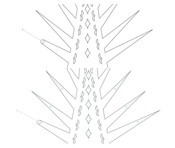
I draw a circle on one of the side spikes to tone it down and add a decorative tip. I only want to propagate this change to the lower 3 largest spikes on both sides of the spoke. I have my first seed cut, so next I will start a new sketch on the front plane and place some points.
Notice that I have reference geometry all over the place, but the tool will put instances only on the sketch points. This means if you want to put instances on the endpoint of a line, you’ll have to put a sketch point there.
Here is the result from the operation. If it asks you to select bodies, that means you cut the model into several bodies and you have to choose which ones to keep. That’s okay, usually the first selection is the largest piece (the middle part we want) so I select body 1 and get rid of the trimmings.
6. Circular Pattern
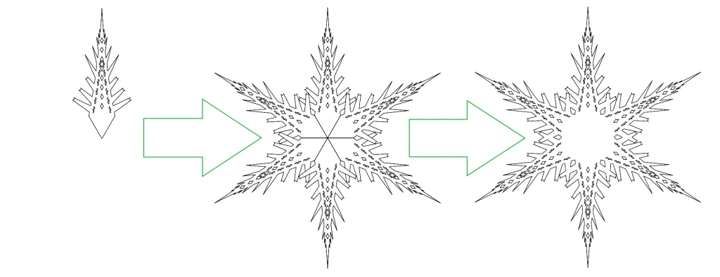
Here’s the moment we’ve all been waiting for! Let’s get this one spoke into six. Select the bottom edge as the direction to go around. Alternatively, create an axis to pattern around. Set 6 instances over 360 degrees, specify equal spacing and then hit OK. You’ll notice that there are a couple of edges going through the middle. If you look over at the Feature Manager Design Tree, you’ll notice that the Solid Bodies folder has six members. The body pattern created separate bodies. To combine all of them into one body, use the Combine command. Fire up the Combine command and make sure it is set to add. Select all six bodies and hit OK. The result is one snowflake that is starting to look awesome!
7. Table Driven Pattern
If we happen to have a list of coordinates of points in a text file, we can use it to place the center of a patterned instance. I just so happen to have this comma delimited list of X-Y Values in .txt format.
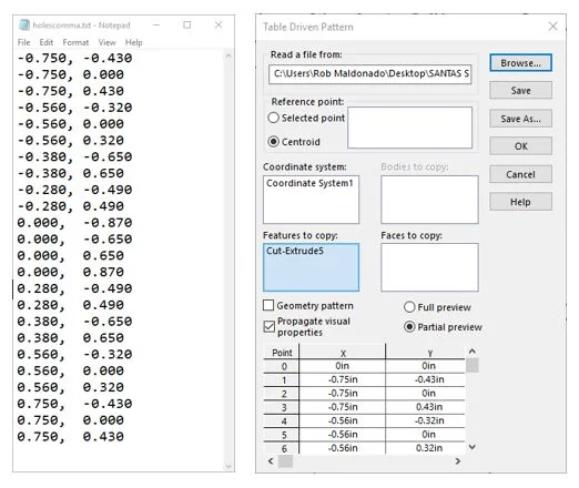
It’s a pattern that fits pretty well in a hexagon, so I will use this to decorate the center of my snowflake. To use these with a table-driven pattern, we need to specify a coordinate system to use these numbers against. Even though the coordinate system is the same as the default one, I will create a new one so that I can select it for the pattern.
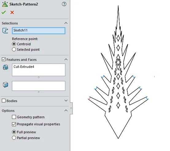
Next, I make this 12-pointed star cut right at the center of the snowflake to be our seed instance. Launching Table Driven Pattern, we get a window as shown. First, hit browse, change the file type to .txt and browse for the .txt file and hit open. You should see the file path populate the box. For reference, I will leave it at centroid (i.e., I want the center of the star at every point). Then under features to copy, select the cut. We now have all our stars placed at every single coordinate. Cool!
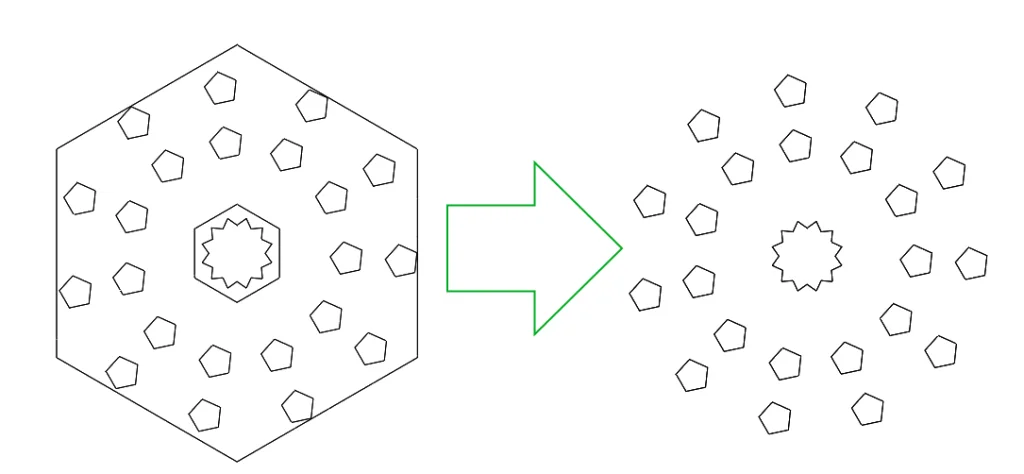
8. Fill Pattern
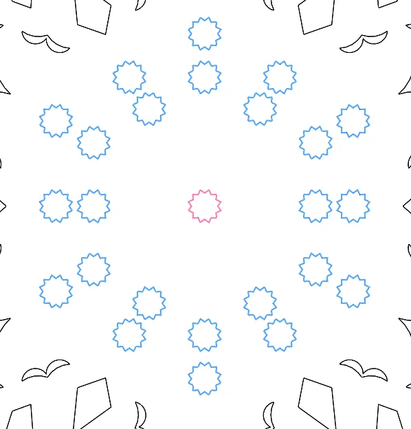
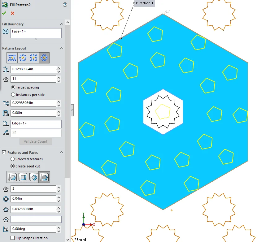
The snowflake is looking pretty good! The only issue is that there is some empty space on the top surface between the center star and the other instances that surround it (shown in blue in the image).
So we will fill this area with cuts. Luckily, SOLIDWORKS has a tool for this. We can fill an area with instances with Fill Pattern! The first step is to bound the instances by splitting the face into the region we want to fill. A sketch and split line should do the trick, and the result is the blue face in the same image. Fill Pattern has the ability to create seed cuts, so we can go straight into the command without making a seed instance. Under features and faces, select create seed cut, and I chose pentagons with a circumscribed circle diameter of 0.04 inches. The fill boundary is the split face. I played around with the setting until I got what I liked. Check the screenshot for exact settings!
A byproduct of using split line to define the fill boundary is that the face remains after the operation is completed. If a clean surface is desired, launch the Delete Face command, select the “Delete and Patch” option, select the split face and hit OK. Voila! The face has been patched over.
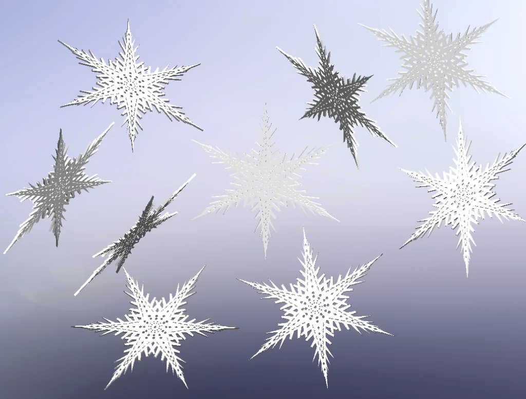
Thanks for following along. Now let’s make it snow! Post your snowflake challenge result in the comments below. I’d love to see them!
Author: Robert Maldonado, Application Engineer at DesignPoint