
Setting up your simulations is a straight forward process made up of just a handful of steps like defining your materials, loads, and fixtures – capturing the real-world environment as closely as possible. And before you can move on to the most important step of meshing, you need to define your contacts. This is where you define how two components or bodies interact with one another. How you define these contacts, or interactions has implications on the way the geometry is meshed. Here’s how.
When setting up a static simulation or a basic strength test, there are three options for defining contacts:
- Bonded
- No Penetration
- Allow Penetration.
But incompatible and incompatible meshing pertains to only one of the contact conditions – Bonded. When you have bonded contacts, the geometry is treated as though it were perfectly connected, like one solid piece. This can be done automatically with a global, all-over condition or manually with local contact sets. Unique to bonded contacts is the concept of a compatible or incompatible mesh.
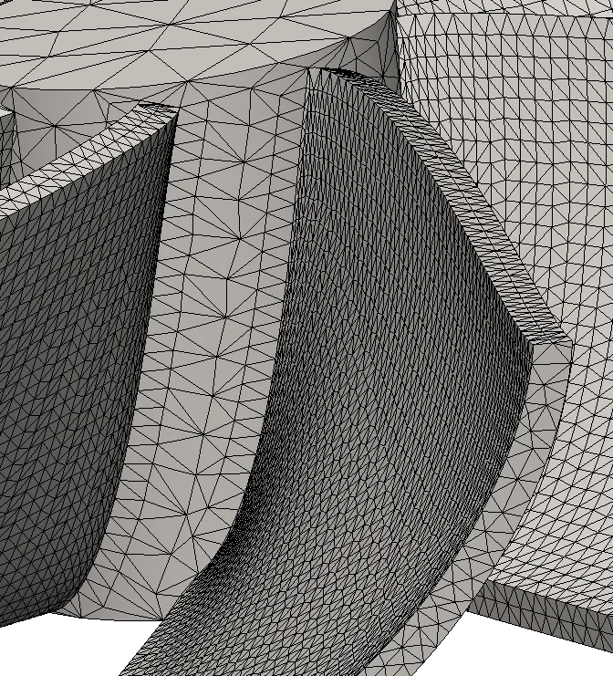
The actual “bonding” or connections will be created by the mesher. At the interface of bonded components is where the concept of compatible or incompatible comes in to play. Compatible or incompatible meshes can be simplified like this – will the components be meshed the same or different?
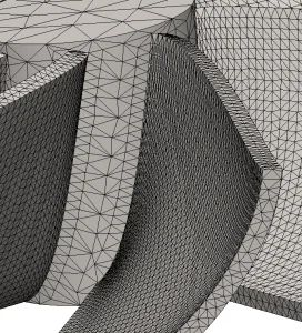
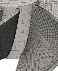
When the elements on each component are the same size you’ll have what’s known as a compatible mesh. If they’re different you have an in compatible mesh. As mentioned earlier this is unique to bonded contacts. With bonded contacts there exists the opportunity for element nodes at the interface to be merged forming the bonded contact. This is the cleanest way for a bonded contact to be created but isn’t always possible. Sometimes the geometry just won’t allow for this, for example when the shape and size is dramatically different. In this case the bonded contact is created through additional contact elements instead of the mesh elements.
Dealing with Mesh failures
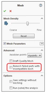
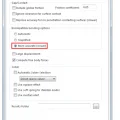
When dealing with mesh failures of your assemblies it’s a good first step to think about using an incompatible mesh. A vast majority of mesh failures can be addressed using an incompatible mesh because the components are meshed individually with the appropriate elements and then connected using special contact elements. It’s such a common fix for mesh failures that there’s an option to automatically remesh failed components using an incompatible mesh. This option can be set through the simulation system options. But if you prefer to go through the mesh failure diagnostics, the option is there too.
Incompatible Mesh Options
Regardless of whether the elements on both components are the same, the fact remains – the components need to be bonded. If an incompatible mesh is used, then the bonding is done through those special contact elements. SOLIDWORKS Simulation has two different algorithms to handle the bonds between bodies with an incompatible mesh – simplified or more accurate.
Option 1 – Simplified Bonding

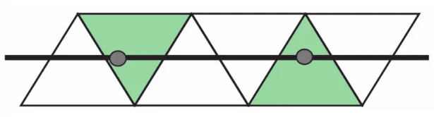
The simplified bonding algorithm is node based. When creating bonded contacts with this algorithm, the source body is represented using its nodes, while the target is represented through the element faces. But the only elements that participate in the bonding are the ones upon which a node directly lies. Because of this, the mesh density has big implications on this type of bonded contact. When there are more source nodes and target elements then there will be more contact elements created. In the image below the contact elements are created within the elements in green.
Option 2 – More Accurate Bonding
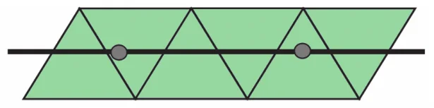
The more accurate bonding algorithm is also known as the mortar method. With this algorithm the source entities use the full description of the geometry not just the nodes. This means that the edges of the source not just its nodes participate in the bonding leading to complete and accurate description of both the source and target. In the image below the contact elements are created in the elements within green.
Automatic Bonding Method
Can’t decide which algorithm to use? Use the automatic setting. When the automatic option is selected, the software will decide which is the most appropriate bonding type with respect to the model and solution times.
It is things like this that really make SOLIDWORKS Simulation such an easy tool to use. The automatic settings for thing like the bonding algorithm, solver, and even the automesher are such powerful tools that they take the tedious guess work out of FEA. Even degreed and experienced engineers (like the one writing this post) find themselves using the automatic settings to make things incredibly easier and much faster. I even was able to leverage these settings to quickly set up and run a simulation in the middle of the Peruvian desert. Check out the video below.