

Every version of SOLIDWORKS contains SimulationXpress capability to carry out first pass stress analysis on your parts. If you are lucky enough to have SOLIDWORKS Premium, then you also get the linear static analysis simulation add-in. In addition to this, SOLIDWORKS offers a number of simulation add-ins that run within Simulation Standard, Simulation Professional, and Simulation Premium; each provides the user with more simulation capability from basic linear static analysis in Simulation Standard, through to non-linear and dynamic analysis in Premium. Now this raises a question with regards to the role of SimulationXpress especially given that on opening SimulationXpress the blurb contains this paragraph:
Does that mean SOLIDWORKS SimulationXpress is essentially useless? A gimmick included in SOLIDWORKS to allow users to create pretty colours on their models? The answer to that is definitely no, SOLIDWORKS SimulationXpress does have a purpose and actually depending on your model and your analysis setup could present you with the same results as SOLIDWORKS Simulation.
So what is SimulationXpress?
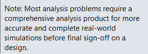
SimulationXpress is a wizard based simulation module within SOLIDWORKS; we assign a material to our model, apply fixtures and loadings, and then run the simulation to solve the problem. It uses a principle called Finite Element Analysis (FEA) to break a big problem down into smaller more manageable pieces, or elements, comprised of multiple nodes (a process usually referred to as meshing). Calculations are then undertaken to determine the displacement and stress at each node, the results of which are then presented as a set of results. These results can be used to check whether the part will withstand the loads applied to it, identify failure points if they exist and allow us to further refine the model if required to improve our products. This whole process is undertaken much quicker than hand calculations could be carried out or even manufacturing a test piece and physically testing the part.
From CAD Geometry to FEA Results
So what can I do in SimulationXpress?
SimulationXpress has some limitations which don’t exist within the other simulation packages; these can be split into four main areas: geometry, loads/fixtures, meshing and finally results.
Geometry
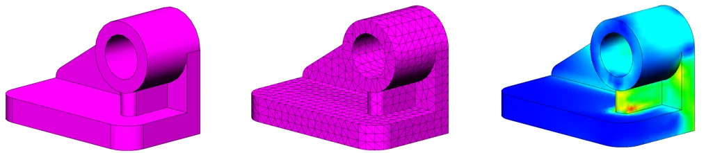
SimulationXpress can only analyse parts, it cannot deal with assemblies or multibody parts. This may potentially not be a show stopper for some users who only wish to test a part in isolation rather than a collection of parts. There’s also little stopping us combining all the parts in our assembly together to bypass this limitation, however this will assume that the parts are rigidly bonded together which may or may not be a real world scenario. This approach may artificially stiffen the model by assuming that parts are bonded together and this will have an effect on the validity of the results (assuming a bolted joint is rigidly glued together is a huge over simplification of a problem for example). In the full simulation package you can specify different contacts between parts and you can also apply connectors to simulate pinned, bolted and welded joints to more accurately represent the real world scenario.
SimulationXpress cannot handle Multibody Parts or Assemblies
Loads/ Fixtures
SimulationXpress allows users to only rigidly fix models by faces; this might not truly represent the real world fixture on the model and again lead to an artificially stiff model. Similarly with regards to loads we are limited to only applying force and pressure loadings to faces, in Simulation there is a wide range of different loadings that can be applied.
Meshing
The FEA process involves splitting a model into many small elements, within SimulationXpress we only have one mesh type available to us (Standard) and that mesh size is Global across the entire model. With the Simulation add-ins we can specify mesh controls to force finer meshes in areas of interest whilst using a more relaxed and coarser global mesh in other areas, this means fewer calculations and quicker results, we would have to have more elements in a SimulationXpress model for this reason alone as we have to choose a mesh size that’s appropriate for the whole model as our global size, leading to longer solution times.

SimulationXpress allows only a global mesh size in Simulation we can put local mesh controls into our FEA model.
Results
Within SimulationXpress we are limited to three output plots: stress, displacement and factor of safety plus a deformed view of the model, we can output a report in both eDrawings and Word formats. The kicker with this is we have very little control over these plots (over and above picking SI or English IPS for our units) we can’t even change the unit display, this might be a limitation if you are interested in further analysis of different plots such as principle stresses, deformation in a known direction etc. The full SolidWorks simulation packages allow you much more control of the study results.
The above may or may not deem SimulationXpress as unsuitable for your requirements but it is important to realise what SimulationXpress is, it’s a first pass stress analysis tool, giving the designer a quick insight into potential issues early in the design process.
Results Comparison
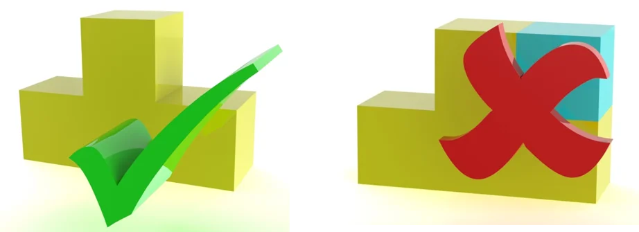
Well this is the surprising bit; the mesher and solver used to solve a SimulationXpress study are the same ones as used for full SOLIDWORKS Linear Static studies so it’s not like you are getting reduced quality in regards to the algorithms used to mesh and solve your study. For simple models (single parts) with simple fixtures the results are identical.
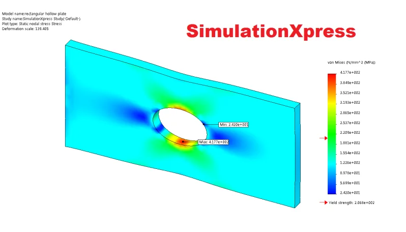
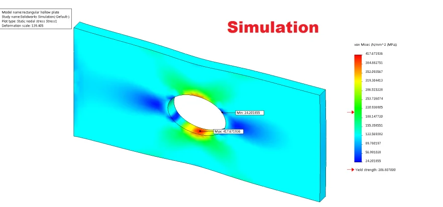
This example is a simply restrained plate in tension. The results are identical for both stress and displacement (417.67MPa and 0.143mm). Therefore its accurate to say that if all you are interested in is running simulations on single body parts, where fixtures are only fixed geometry with simple force or pressure loadings then SimulationXpress is suitable for your needs, it is likely however that these restrictions may cause inaccuracies in your results (over stiffening of a structure due to inaccurate fixtures for example) or due to the lack of mesh controls studies take a long time to mesh and solve.
Obviously if we want to look at assemblies of multiple components with specific contact conditions between each component or you want more control over the entire analysis and post processing then we will need to invest in SOLIDWORKS Simulation.
Conclusion
As with any of the Xpress products in SOLIDWORKS these tools are there to give users an insight into other areas of functionality within SOLIDWORKS. They are designed to be cut down versions of their big brothers and sisters with clear and known limitations. If we work within these limitations and use the products for their intended purpose (to be first pass ‘insight’ tools) and we end up with a better understanding of our design from earlier in the design process this will only leave us with a better end product. Whilst that end product might need to be run through the full SOLIDWORKS simulation suite before sign off the Xpress tool has still been invaluable in the process and it’s absolutely free within our SOLIDWORKS package.