How to Create and Use Custom Appearances in SOLIDWORKS


A vast library of appearances and textures are included in every SOLIDWORKS install. Additional ‘out-of-the-box’ appearances can be added or created, however. Read on to find out how…
Adding
There are over 10 different file types that are recognized as image files within SOLIDWORKS and are therefore usable as custom appearances. Any image can be used, even a photo taken by the user. Which is especially useful if the user wants to see their product within its natural environment.
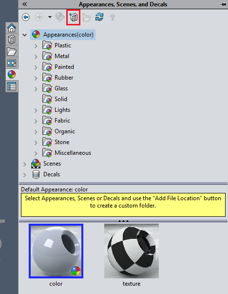
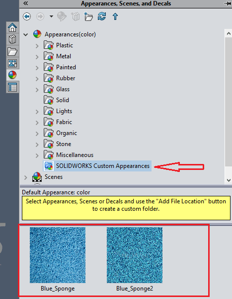
In order to use these images, all you have to do is save them in a location of your choice i.e. “Documents” and select the “Add file location” button as shown below in Image 1, then select the folder that the files are in. This should then populate the bottom half of the task pane with the containing image files, see Image 2 below. These appearances can then be dragged and dropped onto the model and specifying the level that you want it applied to; face, feature, body, part/assembly.
Creating
Alternatively, instead of using an image file of your choice, an existing appearance can be manipulated in order to achieve the desired result.
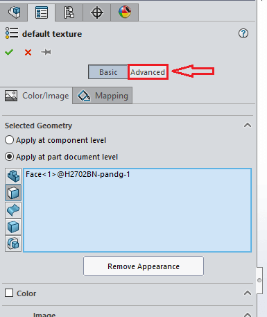
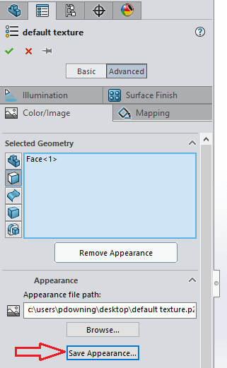
To achieve this, right-click on the appearance in the Appearance manager-> edit appearance. In order to manipulate the appearance and generate a new separate appearance, the advanced button needs to be selected, as shown in Image 3. This enables the user to change the path for the texture file, as seen in Image 4, and also enables two additional tabs; “Illumination” and “Surface finish”.
Illumination
This tab consists of a number of slider bars enabling the user to alter the image in a variety of ways i.e. transparency, reflection, etc.
Surface finish
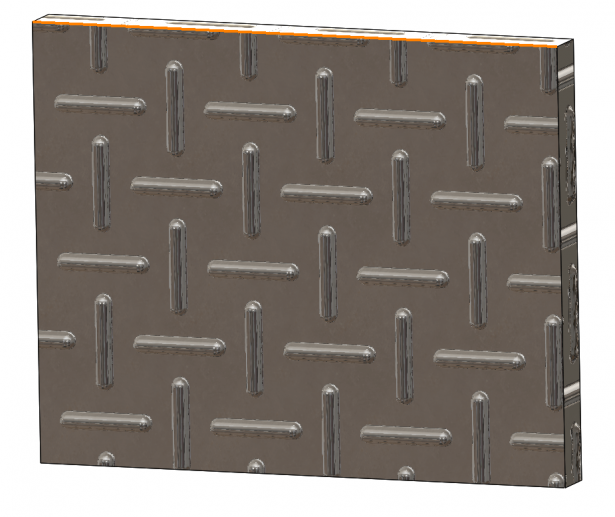
On the surface finish tab, there are a variety of choices, each of which presents the user with a completely different texture on the appearance. For example I have applied the “Treadplate 2” texture to the face of some geometry and it appears as follows;

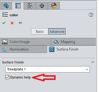
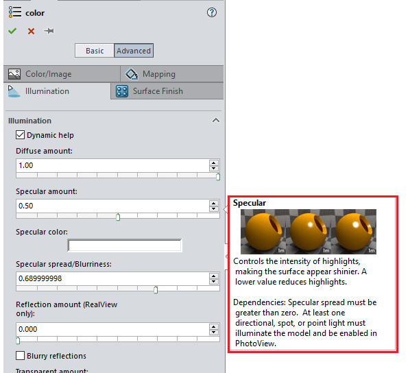
In order to find out what each of the commands does, by toggling on “Dynamic help” as seen below in Image 6. By hovering over the commands, the user is presented with a visual illustration of what the command does.
If the required texture is not present amongst the drop down list, you can add your own when selecting “From file” amongst this list. Note this is just an appearance, the geometry of the part does not necessarily change. The two methods used of displaying these textures is either “Bump mapping” or “Displacement mapping”, as seen below.
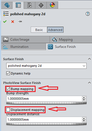
The basic difference between the two techniques is that bump mapping does not manipulate the geometry, it only uses lights and shadows, whereas displacement mapping does manipulate the geometry in order to obtain the texture.
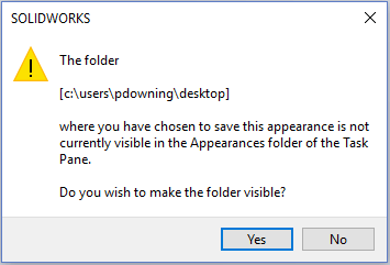
Once the appearance has been manipulated to the users requirement, it can then be saved as a separate appearance file (*.p2m) as shown in Image 9. If the location chosen is not being pointed to by SOLIDWORKS then the following message is displayed, it can then be added:
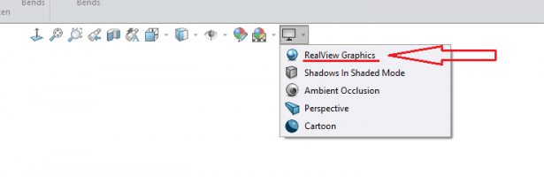
RealView Graphics
RealView Graphics is required to display the bump mapping result, as shown below. Displacement mapping is mostly used for rendering. If RealView graphics is unavailable, it is most likely because you do not have a compatible graphics card. Check certified graphics cards and drivers by clicking here.
Latest posts by Innova Systems (see all)
- Duplicating a SOLIDWORKS Assembly Project - August 20, 2018
- SOLIDWORKS 2018: The Bounding Box tool - July 24, 2018
- The Misaligned Mate in SOLIDWORKS 2018 - June 16, 2018