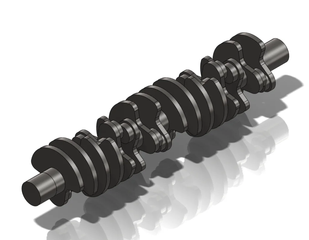

In this fourth post about the W16 Engine I will introduce the Crankshaft and detail its build.
See detailed explanation in the extended entry at the end of the post.
Thank you for reading about this build and stay tuned for the next post which will include the Block-Crankshaft-Pistons assembly and its animation.
George Bucsan
Worcester Polytechnic Institute
Aerospace Engineering, 2014
The build of this part is modular. I built three main parts and simply added and duplicated them in an assembly.
The first part, the main axle, is a cylinder with a diameter of 1.93 inches and a thickness of 0.87 inches. It also has a central axis to facilitate the mating process.
The second part is comprised of the counterweight and the offset axle to which the conrods connect. I will name this part simply Offset Axle. The cylindrical side of the part has the parameters: diameter = 0.144’’, thickness = 0.5’’. The counterweight part is an extrusion, with a thickness of 0.39’’. Its sketch has two basic features: it has a semicircle of radius R=2.54’’ that is concentric with the main axle projection and it has a semicircle concentric with the previous extrusion, but with a slightly bigger radius (1.8’’). The rest of the sketch is comprised of tangent arcs used to close the sketched profile.
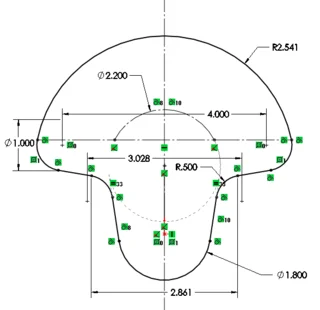
Through the center of the big semicircle I created a Central Axis which I will also use for mates in the assembly. On the surface of the offset axle I added a sketch and drew a vertical line to help me visualize the angles while in the assembly. Because I will also flip the part while duplicating it within the crankshaft assembly, and because flipping it rotates the right plane by 180°, I copied the file, saved it with a different name and slightly modified it. I created another plane, at an angle of 180° from the Right Plane and called it Flip Right.
The building part is almost done by now, as all the needed components are available. The only problem is calculating the phase angles between the Offset Axle (/Flip) parts. The reference file I used throughout this build refers only to W4/8/12 engines, but explains the algorithm for determining the phase angles well enough to be understood by someone with no engine experience.
Calculating the angles:
If we assume that all the pistons are placed in a row, the Offset Axle parts would be at 360°*2/16=45° sequentially relative to each other. Because the engine is a four-stroke, each complete cycle represents two complete revolutions (2*360°). Because the pistons have to be balanced, this angle is divided and distributed to the phase angles, in other words, the phase difference between two consecutive pistons the same: 720°/16=45°.
Unfortunately, this engine is not in a straight-16 configuration. In the reference document, the VW engineers explain the algorithm for determining the crankpin offset. When applied to this engine, it looks like this: 72°(the V angle between the main banks) – 45° (the above determined phase angle) = 27°. This crankpin offset angle represents the additional phase angle that needs to be adjusted into the offset axle parts corresponding to the pistons on the right banks (considering that we start counting the cylinders from the left side).
The firing order of this engine is based on another way of counting the pistons (the new one on the left, the initial – the order on the crankshaft – on the right):
7 8 15 16 13 15 14 16
5 6 13 14 9 11 10 12
3 4 11 12 5 7 6 8
1 2 9 10 1 3 2 4
Firing order by using the new method of counting:
1, 16, 7, 10, 3, 14, 5, 12, 2, 15, 8, 9, 4, 13, 6, 11
This can be translated into the initial method of counting:
1, 16, 13, 4, 5, 12, 9, 8, 3, 14, 15, 2, 7, 10, 11, 6
Using the above firing order, I know how much phase angle to add to each offset axle. I will consider the first offset axle to have a phase angle of 0°. Then, the piston with number X has a corresponding offset axle phase angle of (X-1)*45°. Now I have to account the crankpin offset of 27°: the angles for pistons on the right side are 27° bigger than their corresponding pistons on the left (1-2,3-4,5-6,7-8, and so on).
The repeating set of angles for the left side is: 1-0, 3-90, 5-180, 7-270 (9-360). Therefore, the repeating set of angles for the right side is: 2-27, 4-117, 6-207, 8-297. Overall, the angles for the first half of the crankshaft are:
1-0, 2-27, 3-90, 4-117, 5-180, 6-207, 7-270, 8-297
The second part is identical because of the periodicity.
Because of this feature, I constructed the crankshaft as an assembly consisting of two half-crankshaft sub-assemblies.
For the Half Crankshaft assembly, the procedure only implies mating parts and planes. I inserted four instances of each file: Main axle, Offset Axle and Offset Axle Flip. The mating order of the axes in each part alongside the central axis is periodical: Main axle, Offset Axle, Offset Axle Flip. After this, I mated the right planes of the parts at the angles specified above (in bold). Finally, I mated the front and rear surfaces of two adjacent parts. In addition, for the Offset Axle Flip part I created and used the plane called “Flip Right”. I could have used the original right plane, but because of the flip I would have to add 180 additional degrees, therefore making adjusting and bookkeeping more difficult. The Flip Right plane is defined from the Right Plane, at an angle of 180°.
For the Crankshaft assembly, I inserted two instances of the Half Crankshaft assembly and mated the back surface of the first one with the front surface of the second. I also made their right planes, front planes and top planes parallel in pairs (Parallel Mate).
Later in the build, I needed the ends of the shaft to be longer, therefore I created two copies of the Main Axle part and modified their names and lengths: Main axle medium (L=1.63’’) and Main axle long (L=2.5’’). These lengths were adjusted after I placed the Crankshaft in the Block and I measured distances between surfaces. I added these two parts to the ends of the prior assembly, mated them on the central axis, and locked them into place.