
W16 Engine: The Block
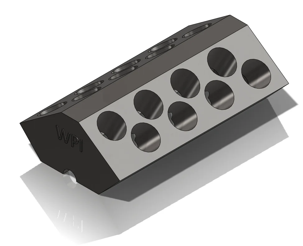
In this third post about the W16 Engine I will introduce the Engine Block and detail its build.
See detailed explanation in the extended entry at the end of the post.
Thank you for reading about this build and stay tuned for the next post which will include the crankshaft and the math behind it.
George Bucsan
Worcester Polytechnic Institute
Aerospace Engineering, 2014
The main characteristic of this engine block is that it has four banks of cylinders. I will number them 1-4 (left – right) to make keeping track of them easier. I will first create an enlarged engine block with five upper surfaces, four of them perpendicular to the cylinder planes (ideal for making the holes) and one of them horizontal. The geometry of the cylinder banks is: the big V angle = 72°, the small V angles = 15°. This translates into the angles of the cylinder planes: 1st = -43.5°, 2nd = -28.5°, 3rd = 28.5°, 4th = 43.5°. Another important feature is the crank offset of 12.5mm = .492’’. The crank offset refers to the distance between the cylinder planes and the center of the crankshaft – the planes do not intersect on the crankshaft axle!
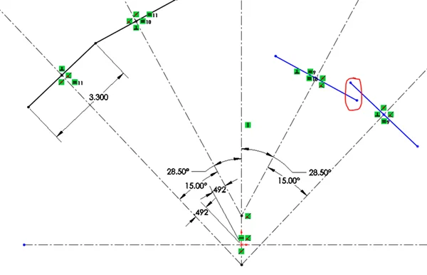
I started building this intermediate block by initiating a sketch on the front plane and drawing a horizontal and a vertical centerline through the origin. Then, I drew four more centerlines, and set them to the angles described above (also see the below picture). Then I merged their bottom endpoints. The next step was to create the crank offset: I set the distance between them and the origin to .492 inches. To begin drawing the outline for the top surfaces of the engine I drew four lines, each perpendicular to and intersecting one of the 1-4 axes in its midpoint (see the below picture). I also merged the ends of the two pairs of adjacent lines.
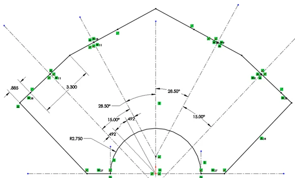
Now that I made the basic shape for the cylinder planes and the block’s top surface, I closed the outline. I extended the 1st and 4th lines by .885inches and then connected them to the horizontal centerline by lines parallel to the corresponding cylinders (centerlines 1 and 4). I then drew two short vertical centerlines from the horizontal line to help me with the construction of a tangent arc, centered in the origin, with radius 2.75’’ (slightly bigger than the crankshaft counterweight radius). Finally, I added two horizontal lines and extended the topmost lines (2 and 3) to close the sketch.
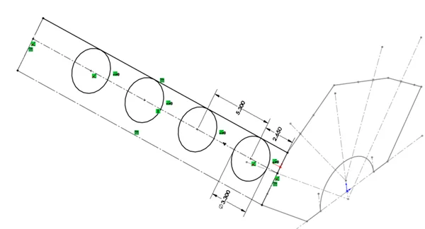
By extruding this sketch 24.35’’ I got my intermediate block. I chose this dimension after I adjusted the cylinder holes and the distance between them; therefore I will explain that in a few paragraphs below. I decided to begin by spacing the first hole 1inch from front edge and the next holes with a distance of 2 inches between. Although the distance between cylinders will remain constant on all four banks, there will be an offset relative to the front plane (edge), therefore the 1’’ dimension will increase with the number of the bank. To create the above described geometry I started with a sketch on the surface for the first bank of cylinders (leftmost) and converted the edges into construction lines. I then drew a line parallel with the two lengthwise lines, through the axis of the first bank of cylinders (on the front sketch). I used that to add a 3.3’’ circle and make a linear sketch pattern with 4 entities. Just to fully define everything I made the center of the 4th circle coincident with the axis of the pattern, and added a smart dimension (5.3’’) between two of the adjacent circle centers.
After extruding this sketch with a Trough all option, I created the same geometry for the following three top faces, with the distances between the first circle and the front edge set to: 5.3 for the 2nd row, 3.15 for the 3rd row, 5.8 for the 4th row. No two cylinders should have the same projection on the crankshaft, as the conrods need to be consecutively added and cannot overlap. The numbers above come from the fact that the offsets between the cylinders relative to the front face are equal to the distances between the pieces of the crankshaft. These two entities (block & crankshaft) are geometrically tied together, therefore the only way of making them is building them separately and then adjusting relative to each other. The drawings in the reference file can provide some basic proportions but are not always correct; therefore some educated guesses are needed.
As a note about the above dimension (24.35 inch): given that the 4th row of cylinders is offset from the front face by 5.8’’(from the center to the edge), there are four holes, 3.3’’-diameter each, spaced 5.3 inches apart (center-to-center), and the offset from the back face needs to be equal to the offset of the 1st row relative to the front face (to keep the symmetry intact), a short calculation reveals the meaning of the 24.35’’ number: 24.35=(5.3+0.5)+(5.3*3)+2.65+1
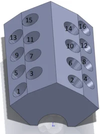
For making the mating of the pistons easier, I created axes through each cylinder. The order I used is the number order seen below. The first piston that connects to the crankshaft is number one, the second number two, and so on, like in the image below.
Because the axes of the cylinders do not pass through the central axis (the crankshaft axis, through the origin) it is difficult to calculate the exact height of the block at this time. Initially, I built the crankshaft, placed it into the block and added pistons 1 through 4. Through a wireframe front view, by rotating the crankshaft and measuring I was able to determine the distance that was between the top of the pistons at their top dead centers (topmost point) and the top surfaces of the block. With those measurements I knew exactly how much to “cut” from the block. Just to be more precise through the (re)build, I copied the sketch from my original file and then fully defined it. Then I extrude cut the sketch through the entire block.
At this point, the crankshaft can be seen from the outside when it is put through the block, therefore I chose to close the front and the back half-holes with two ribs (one rib and a linear pattern). For the rib feature, just draw a line on a sketch on the front face and connect the two endpoints of the half-hole. The thickness I set is 0.87’’ and this is also a dimension I set after I built and fitted the crankshaft. I made a linear pattern with this rib along the length of the block at a distance of 24.35-0.87=23.48 inches.
The remaining important feature is the cut through the previously made ribs that would allow the crankshaft’s main axle to come out of the block and connect to other sub-assemblies of the engine. That was made through an origin-centered circular sketch on the front plane and a through all extruded cut. The diameter of the circle is 1.93 inches, equal to the diameter of the main shaft.
A feature I added when I was building the belts for the camshafts is a hole in the back side of the block that would support a double pulley. Its diameter is 0.76 inches, it is placed 6.5 inches above the origin and the depth of the extruded cut is 3 inches.