Building SOLIDWORKS Sell Assemblies with Conditional Connections


SOLIDWORKS Sell is has a multitude of tools used to create and display a product on an online configurator. These tools help users assemble their models to include all different configurations and geometry changes. Many different strategies can be used to create similar end products. What dictates the processes used in building a configurator is an idea of what needs to be shown and how that going to be accomplished.
One way to configure a template is with the use of attachment points and conditional connections. Attachment points are used to bring together the groups in a template within SOLIDWORKS Sell. Typically, groups are attached to one another with the WCS Origin, a common point of all groups that is dictated by the SOLIDWORKS origin of the assembly or part file. Additional attachment points can either be added within the SOLIDWORKS Sell Project Editor or imported from SOLIDWORKS as 3D sketch points on the individual part files. When an assembly is automatically created after publishing, the WCS origin is used to connect all of the geometries together. Any other attachment points on the parts will be ignored during this process. In order to use these attachment points, the WCS assembly will need to be cleared so the correct assembly structure can be created.
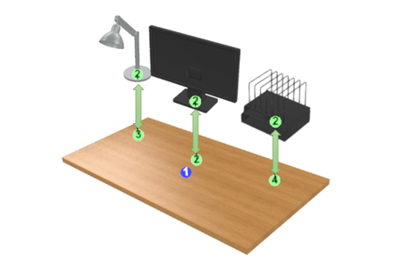
This would be the case for this sample desk (shown below). For this design, it is intended that the customer would have varying add-ons depending on the desk size, including but not limited to a lamp, a desk organizer, and dual monitors. For this variability to be accomplished, attachment points were used to ensure every add-on was in the correct spot for the correct configuration.

In order to accurately configure the desk, every table needed to have the correct number and location of attachment points. This can be further explained with the following image. Figure 2 shows a medium table with its respective add-ons and attachment points visible. The additional attachment points are marked by the green numbers and the WCS Origin for a group is indicated by the blue number. Because the medium table has three add-ons, it needs to have three attachment points that correlate to the location where the add-ons will be placed. The added components will also need their own attachment points so a connection can be formed between the groups. An attachment point form each group is used to connect the two like magnets. Creating these connections will guarantee that groups stay in the correct spots when configurations are changed. In the case of the Sample Desk from the previous image, it ensures that wherever attachment point 3 is, the lamp stays connected to its position. This behavior paves the way for conditional connections.
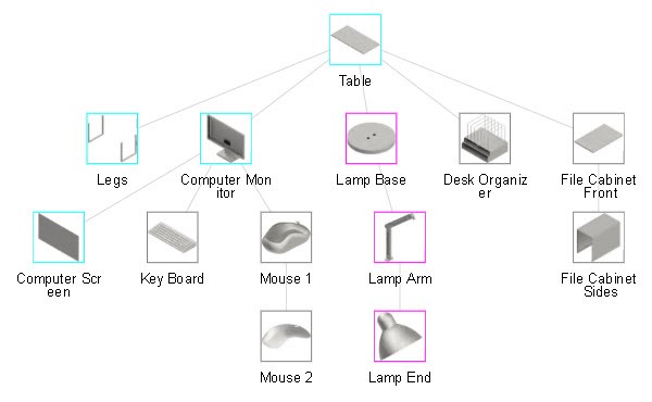
Conditional connections occur when there is an attachment point “missing” from a part, hence the group it’s connected to disappears from the graphics area. If other groups are connected to the group that is initially attached to the table, then these groups will disappear as well. This behavior can be seen though the large size of the Sample Desk, as it’s the only table that has the option for a filing cabinet. Because the cabinet was in an assembly of its own, attachment points were needed to connect the cabinet to the correct spot and ensure it was only available for the large table size. Publishing the cabinet form its own assembly allowed for the groups published to have their own WCS origin. Therefore, an attachment point was used to connect the cabinet to the correct location while the other filing cabinet group was attached to the origin of the first cabinet assembly. These conditional connections produce an assembly structure that looks like a tree roots instead of a circle.
Options can also be used to create a similar functionality to the conditional connections. However, the groups and template used would need to be published in a different manner. Contrary to the previous method, all groups within one size configuration can be published within the same instance of SOLIDWORKS Sell, thus utilizing the WCS origin connections. The difference being that each geometry that changes location and size will need their own groups. This is because, if options are to be used, each group in option 1 is going to need a group to change to in options 2 and 3. If there is a blank space in the option sets, then the geometry from the previously selected option will carry over in the graphics area. These holes can be useful for some groups like the mouse and keyboard because they are staying in the same spot no matter what configuration is activated.
When a gap in the option set that is not necessary, dummy parts need to be created. “Dummy parts” serve as place holders for these gaps in option sets. They are published along with all other components in the SOLIDWORKS Sell Publisher and are typically made of faces not visible to the end user. The dummy part only needs to be published once because it can be replicated into several other groups within the project editor.
Even though the process taken to create an online configurator is up to personal preference, one way may need more fine-tuning than the other in order to achieve the same appearance. For instance, materials may need to match, dummy parts may need to be created, and groups may need to be renamed. Therefore it is useful to know of all the different strategies available to configure a product in SOLIDWORKS Sell.

Rebecca Stafstrom
Latest posts by Rebecca Stafstrom (see all)
- Building SOLIDWORKS Sell Assemblies with Conditional Connections - October 1, 2019
- SOLIDWORKS Sell Expands Augmented Reality Capabilities for Android Users - July 15, 2019
- Material Options Now Greatly Expanded in SOLIDWORKS Sell - June 5, 2019