
One of the key technologies in SOLIDWORKS Flow Simulation is a concept in the software called Goals. My hope in the post is to attempt to clear up any questions that you may have about Goals by breaking it down into 3 sections: first, what is the purpose of using Goals; second, what are the different types of Goals; and lastly, how to define them.
Purpose of Goals
The Goals in SOLIDWORKS Flow Simulation serve 3 purposes:
- Defines Design Goals and/or other important criteria
- Used for Convergence Control
- Finish the calculation
The main purpose of Goals is to define for the project what are the key design objectives for your simulation. Some examples might include maximum velocity in the Y-direction globally or a component’s average temperature. After solving the problem and reviewing the results, you can very quickly ask the software to view a table of your goals or automatically create one in an Excel spreadsheet. This is great for a visual summary of your project. Putting the goal chart to work in the Compare Tool also provides an insightful comparison of results from other projects, where you have either varied the model geometry or a flow parameter. Not the least to mention that while solving the problem, you can view updated values for the Goals in the solution monitor window.
Because the equations governing fluid flow are highly nonlinear, the problem is solved iteratively where the parameters are updated in every computational cell in each solution step. You can track these iterations by monitoring the Goals in both a table and plot. Initially the Goals will change a good bit, but eventually they will not change as much and will begin to level out to some value. The software itself has some built-in functionality for convergence of the solution, but with Goals it gives the user confidence that their key design criteria are accurate.
The solver could run indefinitely, but at some point the solution is changing very little with successive iterations, so you have to end the calculation. And Goals are a great way to indicate that the flow parameters have converged to a certain solution and it is reasonable to finish the solution. Because of the conservative structure of the software, most times this is well before the internal convergence criteria would have stopped the solver, so you save valuable time by defining Goals.
Note that in the above items 2 & 3, I made the assumption that the problem being solved is a steady calculation and not changing with time as transient solution would. Goals are still important in a transient solution as you can still monitor them during the calculation. But know that the parameters may never converge because they are constantly changing in time. And instead of Goals being used to finish the calculation, you typically run the calculation up to a specific physical time for which you then stop.
Types of Goals
There are 5 goal types:
- Global Goals
- Point Goals
- Surface Goals
- Volume Goals
- Equation Goals
A Global goal is a physical parameter calculated in the entire Computational Domain, which is the box that encompasses the entire fluid and/or solid volumes where the solution is solved. One use of a global goal is to find out what is the maximum temperature for all the solid components in the model.
A Point goal is a value at a specific point, and can be specified either by a reference or 3 coordinate values. I personally don’t use this goal very much, but it would be useful to someone who wants to compare the computed results to physical test data at a given point. (Check out the Probe in the Results tools for grabbing computed data on plots at a point.)
Surface goal is a parameter on selected surface(s). Many times I’ll pre-select one of the inlet or outlet boundary conditions to use as a surface for this goal type. If you choose a parameter such as Total Pressure, you can request the min, average, max or bulk average value on that surface; or if you choose mass flow rate, for example, you will get the integral value for the entire surface. Surface goals are very useful for getting pressure drops, as I will explain when talking about Equation goals later.
A Volume goal is a parameter within specified volume(s); it can be applied to parts, components within a subassembly and even bodies within a multi-body part, essentially whatever defines a volume. Like surface goals, you can select more than one surface or volume (depending on the goal type). I often use a Volume goal as a “Component” goal to find the temperature of a specific component.
Last, but not least importantly, is an Equation goal which can be defined using anyone of the previous goal types in a mathematical equation. A very simple example is to subtract a surface pressure the inlet from the surface pressure from the outlet to get the pressure difference, or more specifically a pressure drop for the system. You may also use combine them together to use one equation goal in another. An equation goal is very powerful, as you might gather, because it can be used to calculate such design objectives as Cv (or valve flow coefficient), heat exchange efficiency, pump efficiency, and drag coefficient.
Defining Goals
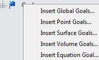
The most direct way to define a goal is to right-click on the Goals icon (a black-and-yellow checkered flag) in the SOLIDWORKS Flow Simulation tree to choose your goal type. You can also do it through a menu following Flow Simulation > Insert and the goal types are at the top of that listing.
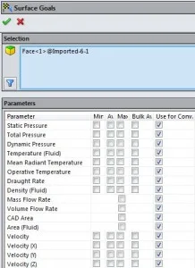
A screenshot of the Surface Goals definition is given above. First, one or more surfaces need to be provided in the selection box. Then you can select any of the boxes next to the named parameters. You see the boxes in columns listed for minimum (Min), Average (Av), maximum (Max) and bulk average (Bulk Av), and the last column is by default selected to include the goal to be used in convergence control (Use for Conv). You may also selected more than one box for min, av, max or bulk av from the list and to define multiple separate goals in the tree.
In this example, since I wanted to use the same face that I had used to define the inlet, you can do the following (which if you click on the animated GIF image below will show you the steps):
After choosing to define the Surface goal and the dialog interface comes up, you may select the Flow Simulation tab at the top of the tree to split and reveal the input items. By selecting the boundary condition that was named “Inlet Volume Flow 1” be default, it will add that same face into the surface goal selection box. Then I define my goal to be an average static pressure goal on that face.
I only provided a general overview on Goals here, as there is much more that I could have delved into each sub-section, but I feel that I achieved the purpose that I set out for this post. Hopefully this post will help you on your way to understanding Goals in SOLIDWORKS Flow Simulation better. If you want to learn more or have questions, please write me comments in the section below.