

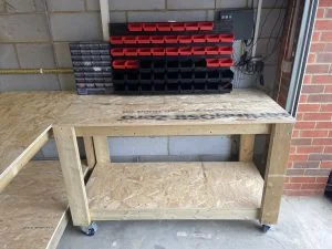
As the dark nights approach, I find myself spending more and more time in my workshop also known as the garage. After years of working on folding tables and countless toes stubbed on what my partner has named “junk that never gets used” I decided it was finally time to use 3DEXPERIENCE SOLIDWORKS for Makers and design some sturdy, usable workbenches to give me the proper maker space that I’ve needed for too long!
Follow along in this blog post as I show you how I used some simple tools and features within 3DEXPERIENCE SOLIDWORKS for Makers to design and make my own set of moveable wooden workbenches.
After taking some basic measurements of the space, I decided I had 3000mm of width to play. I used Google to research the typical dimensions of work benches and found that they are usually a minimum of 600mm deep. With this in mind, I sketched some basic outer dimensions on a notepad and visited my local hardware store to find the most suitable wood to use. I decided on 45x90mm C16 Timber as its strong enough to take the weight of all my “Junk that never gets used”. I would however be using 125mm wide C16 Timber for the upright pieces for two reasons: Number one, is that they’d be taking the full weight of the top surface and whatever I’d be placing on it, and, Number two, the castor wheels I’d ordered had a mounting plate with a 100mm length and this would have overhung the 90mm material. Luckily, I realized this early in the project rather than it catching me out towards the end when I came to fit them!
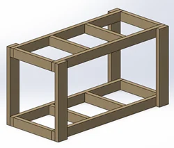
With my frame material chosen and some basic dimensions decided I headed to 3DEXPERIENCE SOLIDWORKS. My first step was to create all the basic timber framework parts that I would be using to create the support structure of the bench. I created a simple sketch in the right plane and extruded to the desired length of 1500mm. This part will form the widest part of the workbench.
Through my day job I’ve learned a handy little trick for making components of the same geometry quickly. After saving the first part I select the sketch upon which the extrude feature was based. From here I alter the sketch plane firstly to the Front Plane and then Top Plane. By doing this alongside altering the extrude distance, I can quickly create parts with the same geometric size in a different orientation. Remember to save between the changes or this handy time saving tip can quickly become a frustrating experience.
Within 5 minutes I’ve got all the parts I need to create an assembly and start joining components into something more recognizable. The other benefit of using planes to control orientation is that when we open these in an assembly, they’re already in the correct orientation to mate together. This means no fiddly spinning around using the triad tool or trying to work out what axis you need to rotate around. After bringing in the few basic components, I use simple mates to line up edges and form the assembly. Rather than importing and mating of the same component multiple times, I use some linear patterns to duplicate items into position. This is a great way to quickly throw together assemblies which contain a lot of repetition or equally spaced fixings such as bolts or screws.
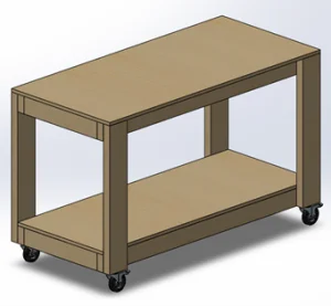
Once I had the basic structure completed, I saved this as a sub assembly before making 2 new parts for the top and bottom worksurface. I decided I would use some 18mm thick OSB board material for these parts due to the good strength-to-weight-to-cost ratio it has. Once modeled I added these parts to the assembly and saved this as Full Assembly. I added the 4x castor wheels into the model for completeness. Thankfully most wheel suppliers allow you to access their CAD files for projects such as this. This is a great way to check fitment and the overall height of an assembly they’re being used on, or to check if hole centers are in the right position before cutting a mounting plate, for example.
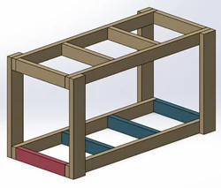
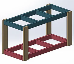
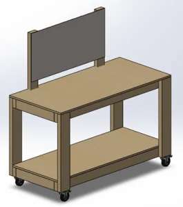
In my making I tend to use a lot of small components on a regular basis; therefore, I wanted somewhere where I could store these easily. Bins have always been great for sorting and storing small things. I settled on a set of bins that would meet my needs and went about adding them into my model. This meant I would be producing two variants of workbench. I created a simple part to mimic the panel used for holding the bin tubs, along with 2 additional pieces of support timber to hold this into the desired position. I chose to save a copy and open the Full Assembly under a different name and set about making the required addition to this model. With some simple mates and a distance mate to set the 1000mm between the external faces of the needed uprights, I mated the panel in place.
With this final piece of the design completed that brought the designing section of this project to a close. Join me in part two of this blog as I get to grips with the making of this project!
To learn more about 3DEXPERIENCE SOLIDWORKS for Makers be sure to click the link!