
In this post about the W16 Engine I will create a partial assembly and make the parts presented thus far look and move like an engine. As usual, this build will be thoroughly detailed.
Download Block-Crankshaft-Pistons
See detailed explanations in the extended entry at the end of the post.
Thank you for reading about this build and stay tuned for the next post which will include the complex Camcase part.
George Bucsan
Worcester Polytechnic Institute
Aerospace Engineering, 2014
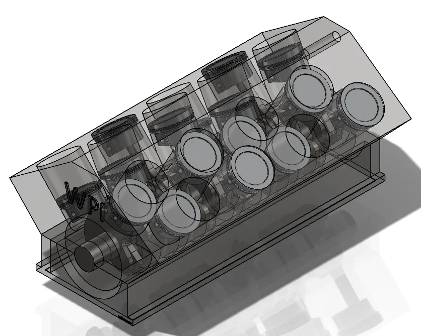
As you can see in the picture above, all the needed parts are already presented, except for the Lower Crankcase:
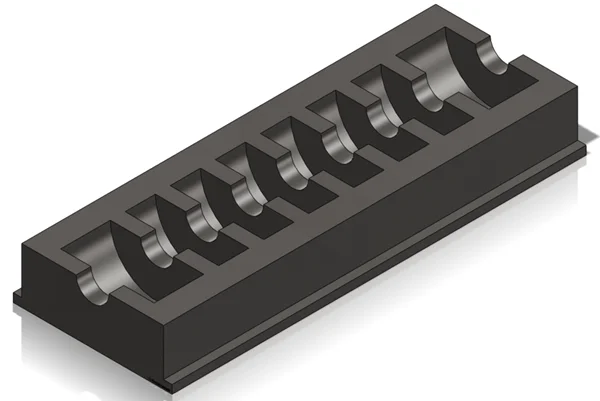
The basic part is comprised of an extruded sketch and a linearly patterned rib. The width of the main rectangular extrude is the same as the base of the engine block and the inner radius is slightly bigger than the counterweights, to accommodate the crankshaft.
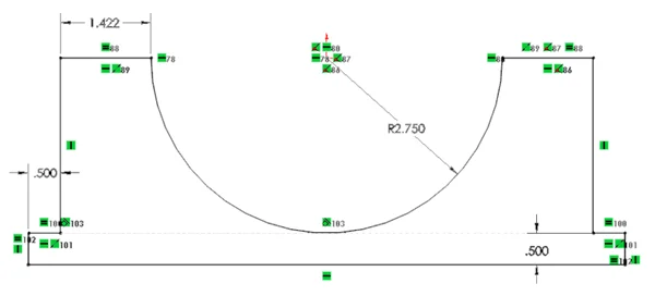
For the rib feature I created an additional plane (Reference Geometry) parallel to the front plane, at a distance of 8.385’’. This dimension is obtained by subtracting the distance between the first and last “main axle” crankshaft subcomponents from the length of the crankcase. This number is later divided by two because the reference plane is the Front plane that passes through the middle of the crankcase.
Each rib is .87’’ thick, same as the “main axle” component of the crankshaft.
The linear pattern of the ribs is made along the longitudinal axis (one can just pick a lengthwise edge of the crankcase as reference) and the distance is the distance between two consecutive “main axle” parts on the crankshaft assembly: 2.65’’. The number of instances is 7.
After creating the middle ribs I closed the ends of the case with two more ribs of equal thickness.
To allow the crankshaft to sit inside the crankcase, I made a circular extruded cut of radius equal to the main axle of the crankshaft through the whole part. The sketch circle is centered at the origin and has a radius of 0.87’’.
To make the part “lighter” I created a shell feature on the bottom side with a thickness of 0.45’’.
At this point, all the needed components are available and ready to be assembled.
Because of the increased complexity, SolidWorks 2010 cannot handle all the piston-rod subassemblies to be mated to the crankshaft and to the cylinders. The easy solution is to make everything simpler by adding all moving parts one at a time into a main assembly. I called that main assembly Block-Crankshaft-Pistons.
The first subassembly is comprised of the piston head, the rings and the pin. I took the Piston-Rings assembly posted a couple of weeks ago and I added and mated the pin. The second assembly is the “Rod” assembly from the same post as Piston-Rings. The third assembly is the Crankshaft assembly. Because these assemblies are not supposed to be flexible, they can be added to the main assembly without having unforeseen mating issues.
The first part in the assembly is the biggest fixed part: the block. The second part (assembly) is the crankshaft. I mated the main axle of the crankshaft to be concentric with the half-circle notch in the block. The next parts are the pistons, all 16 of them. I mated the central axis of each piston with one of the cylinder axes (axis1-16).
For each piston at a time I repeated the following:
– Mate one of the offset axles of the crankshaft to the corresponding piston’s conrod hole (Concentric)
– Mate one of the sides of the same offset axle part with the corresponding conrod’s side (Coincident)
– Mate the Pin to the upper hole of the corresponding conrod (concentric) and pay attention to the upper surface of the piston (it has to be parallel to the upper surface of the block; if it is not, just flip the mate)
The last part added is the Lower Crankcase. I mated its upper surface to the lower surface of the block (Coincident) and then mated the corresponding front and right sides to lock the crankcase in place.
Someone may wonder why the crankshaft was not fixed in the first place. At this time the crankshaft can still move along its axis. The answer is because the crankshaft will be mated to the notches in the crankcase; therefore it will become fixed through a simple coincident surface mate.
After completing this considerable amount of modeling, the enjoyable part follows: the animation. In the lower left part of the SW screen there is a tab called Motion Study. On the motion study screen we see new icons. This time I added a rotary motor to the crankshaft main axle and I selected a low rpm (30) to make the viewing easier. I then dragged the timeline slide bar to 20s to make the animation longer, and saved the entire animation with a setting of 24 frames per second. One important idea here is to let the program play the animation once it calculated it, otherwise it will not save the .avi file completely.