The DimXpert tools in SOLIDWORKS MBD allow you to dimension your parts and assemblies with 3D annotations in order to communicate requirements directly in 3D for the manufacturing process. DimXpert dimensions can show widths, lengths, diameters, and several other features and tolerances so you can fully represent your part. But what if one section of your part needs to have different tolerances than other sections?
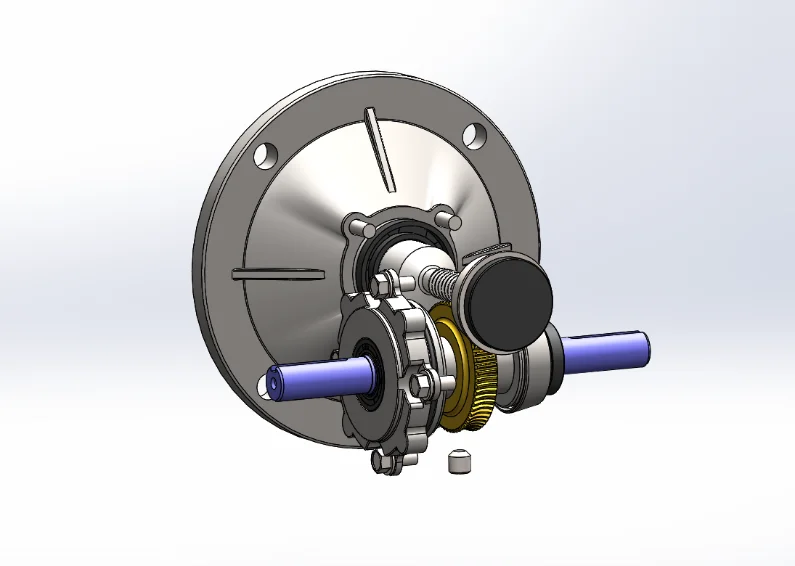
For example, this purple gearbox shaft, shown in Figure 1, is connected to several sleeves, gears, and bearings in the assembly. Although, in order to operate correctly, the yellow gear must be tighter on the shaft than the other parts, so comparatively it needs tighter tolerance values.
One way to do this is to have lower tolerance values where the shaft comes into contact with the gear, and more flexible tolerances for the rest of the body. Adding different tolerance values to a continuous body would result in much tighter requirements than is necessary, and would effectively boost the cost of manufacturing the part because of the amount of precision needed. Having split lines would decrease the cost of the part due to the smaller area where the high precision is needed.

Figure 1: Example Assembly that Needs a Split Feature
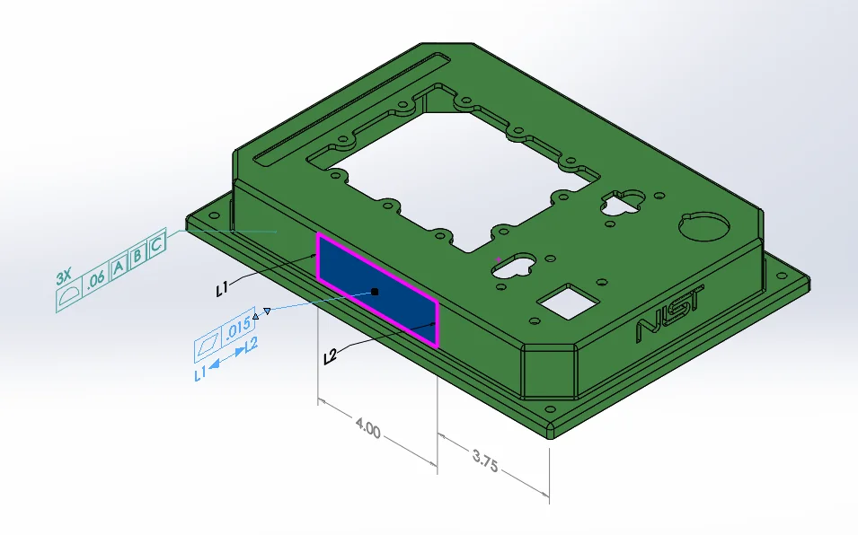
Figure 2: Geometric Tolerance with Split Line
Split lines can also be applied to flat surfaces in order to attach different geometric tolerances. In Figure 2, the split lines create a section of the face where a flatness tolerance has been applied. This means that, while the rest of the face has a surface profile tolerance, this certain area must also be in accordance with a tighter flatness tolerance, too. Again, by adding the split lines, it prevents the machinist from adding precision to the part where it isn’t needed, still reducing the cost of manufacturing. This also saves time in the long run because the machinist doesn’t have to focus on making whole parts with tight tolerances. By only putting in the time to verify that a single section conforms to the restraints, it ultimately saves money for the designers who are getting the part made.
Another reason to use split lines is for datum targets. These help define datums and can be useful for large or irregular parts, especially when parts are molded or casted. Often resulting in uneven, warped, or rough surfaces, split lines and datum targets can show the machinist how the part is supposed to turn out in order to work properly and get the desired aesthetic results.
One thing that is important is letting the manufacturer know where the split lines start and stop. In order for the split lines to be dimensioned correctly, they must have reference dimensions attached to them. These show up as grey in the model area and can be seen in Figure 3 and in the video above. The reference dimension tool is useful for defining geometries like circles, lines, and edges. DimXpert dimensions, however, is unable to define these geometries, and instead they work to define physical features of a product and its geometric tolerances.
Overall, the split line feature can be very beneficial when the design requirements are different on several portions of a single face. This simple tool allows you to add make precise measurements and tolerances that show up in 3D PDFs and 2D drawings. By doing this, it allows for more precise and efficient communication between the design team and the manufacturing team. It can also help cut the manufacturing cost by having only a certain area with high amounts of precision.