

Hello to all,
Welcome to the new edition of the SOLIDWORKS® Support Monthly News! This monthly news blog is co-authored by members of the SOLIDWORKS® Technical Support teams worldwide. Here is the list of topics covered in this month’s Blog :
-
SOLIDWORKS® Inspection: A guide to Edit and Create a CMM Template for your machine
-
How to create BOM with collapsed subassembly in SOLIDWORKS® Composer™
-
Understanding Assembly Constraints in TolAnalyst™
-
SOLIDWORKS® Sheet Metal: Benefits of Gauge/Bend Table and rules to use them correctly
1. SOLIDWORKS® Inspection: A guide to Edit and Create a CMM Template for your machine
– Gaurav GAYAKWAD
In this article, we will focus on steps to take in order to create a CMM Template which can read data from your CMM machine. We will also see how to open and setup CMM Task Pane to work with same.
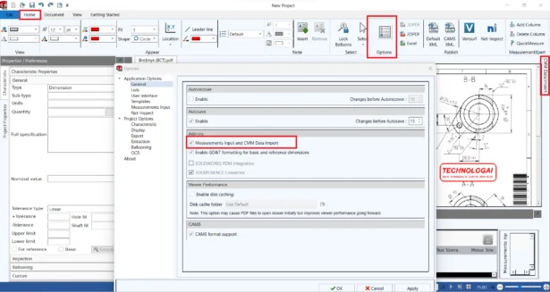
OPENING THE CMM TASK PANE
- In SOLIDWORKS® Inspection Professional standalone, open your inspection project.
- To turn on CMM Data Import, go to Home > Options.
- Go to the General page.
- On the General page under Add-ins, select the Measurements Input and CMM Data Import option > Apply > OK.
- On the right side you will see CMM Data Import task pane.
SETTING UP CMM TEMPLATES
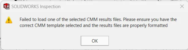
In order to read the CMM data, we first need a template (.xml) which can read the CMM data outputted from machine (like ‘Dukin.txt’ generated from Dukin’s CMM machine). If there is mis-match in the template that we are using and the CMM file that’s generated, it will give us and error ‘Failed to load one of the selected CMM results files. Please…..’.
Now this error could be due to following two reasons:
1. Machine is available in default template list :
First, we will check if SOLIDWORKS Inspection already has the template to read our CMM data (Dukin.txt).
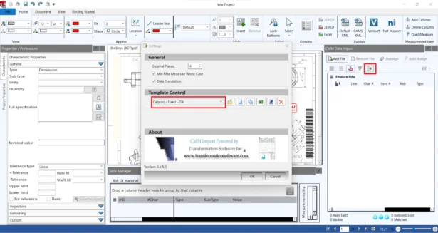
To do so please go to the ‘CMM Data Import’ task pane, click ‘Settings’. In the ‘Settings’ dialog box, to view a list of existing template names, under ‘Template Control’, click the drop-down arrow. Here you will find template list for more than 60 CMM machines. If you see the name of your CMM machine that please select.
If you do not find your machine in default list, please see refer word file ‘CMM Template List‘ where I have shared list of some template that were built internally. If you find your machine, please create an SR asking the Template file (.xml).
2. Machine is not available in default template:
If your machine is not available in any of the lists of default templates. We will have to create a new template as per the output data of your machine, by editing any of the existing template which is close to your machine output.
Please download and refer the attached pdf file (Part1 and Part2), where we have explained on how to edit various templates for different machines. Following this you can create template for your machine. If you find any difficulties or any issues please contact Technical Support.
2. How to create BOM with collapsed subassembly in SOLIDWORKS® Composer™
– Rohit CHAVAN
As we all know, while creating Bill of Materials (BOM) in SOLIDWORKS®, we have multiple options like Top -level only, Parts only, Intended, which allows us to create a BOM as per the requirement. When we create BOM using Top -level only option, only the sub assembly name is listed in the BOM table along with the other top level components of assembly. Sub assembly components are not displayed. Similarly with Intended option, we have the provision to expand or collapse the sub assembly, where as per the requirement we can show or hide components of sub assembly accordingly.
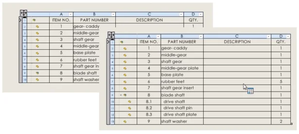
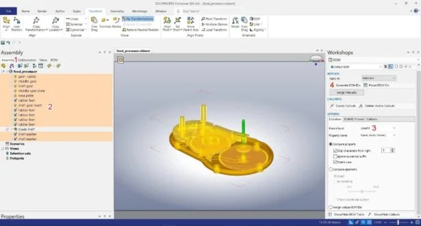
In SOLIDWORKS® Composer™, though we don’t have direct option to display only the sub assembly name in BOM table, this is possible in Composer™ with appropriate workflow. Normally when we create a BOM in Composer™, BOM table lists all the parts in sub assembly also, along with the parts in top level assembly, that is similar to option ‘Parts only’ in SOLIDWORKS®, as you can notice in the image below.
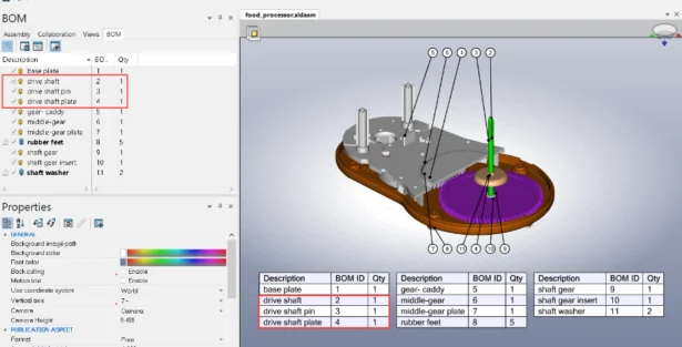
But many of our customer’s has the requirement that, they only want to list the name of sub assembly instead of displaying all the parts in it, mostly because many of them use standard sub assembly procured from third party vendors, so they don’t want to lists its components in detail.
So in today’s blog, we will see, how we can create BOM with collapsed sub assembly.
In general, to create a BOM table with collapsed sub assembly, initially select that sub assembly, set the parent level accordingly as per requirement, generate BOM Id. If you have multiple sub assemblies, repeat the same process for each sub assembly one by one. Finally, select all the other components and follow same process, and finally create callouts and BOM table.
Let us understand this process in detail with an example:
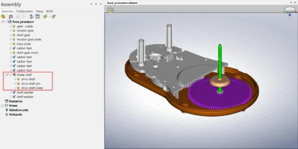
Consider a sample ‘food_processor’ assembly, it has one sub assembly named ‘blade shaft’ which further has 3 components. Now we want to create BOM in such as way, that in BOM table, only the sub assembly name ‘blade shaft’ should be created along with other top level assembly components.
So to achieve this, import the assembly in Composer™, go to Workshops > BOM > in Workshops Pane > under BOM IDS > Apply to > select Selection > under OPTIONS > Definition > Parent Level > select Level 1 > in Left pane, switch to Assembly tab > select the sub assembly blade shaft > click Generate BOM IDs.
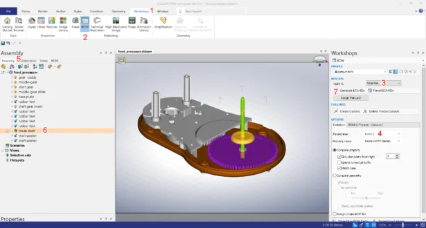
This will generate one single BOM ID for the sub assembly. You can view it in BOM tab in left pane. If you enable the Show/Hide BOM Table button, you can view the same in BOM table. Please note, here the ‘Parent Level’ selection is very important while creating BOM ID, as it specifies whether to create the BOM description from the actor itself (level 0) or from a parent.
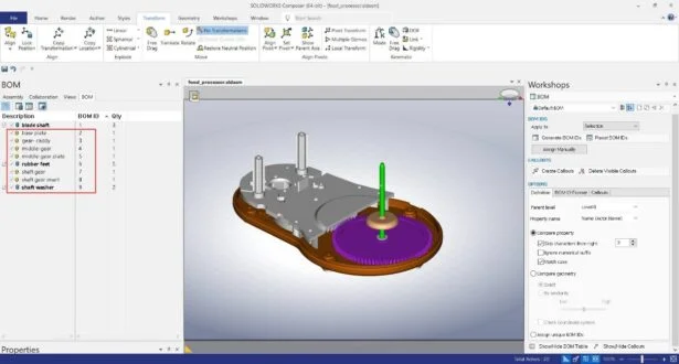
Now again switch to Assembly tab in left pane > select all the other top level assembly components (i.e. all the components except the sub assembly) > in Workshops Pane > under OPTIONS > Definition > Parent Level > select Level 0 > under BOM IDS > click Generate BOM IDs.
This will generate the BOM IDs for all the other top level assembly components, which can be viewed in BOM tab.
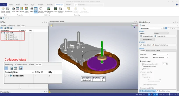
Now the BOM IDs are generated for all the components as per our requirement. Now comes the last part where we need to generate callouts, show the BOM table in the graphics area, and adjust its size accordingly.
To achieve this, select the whole assembly from the graphics area > under CALLOUTS, click Create Callouts > click Show/Hide BOM Table. Once the BOM table is displayed, select it and adjust its size from the Properties pane under TEXT > Size
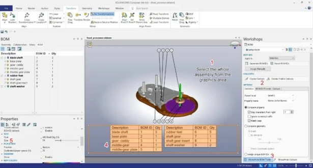
So this finally completes our process. You can notice in the image, BOM IDs are generated for all the components, similarly for sub assembly also single BOM ID is generated and only the sub assembly name (i.e. blade shaft) is displayed in BOM table.
3. Understanding Assembly Constraints in TolAnalyst™
– Tanmay KULKARNI
In SOLIDWORKS® and its tools like TolAnalyst, knowing about assembly constraints is crucial for getting designs right. Sometimes, you may find that assembly constraints aren’t available for some parts while working in the TolAnalyst tool. Let’s explore why this happens.
Why Tolerance Information Matters?
Tolerance information tells, how parts fit together in an assembly. It defines acceptable variations in size and shape, ensuring parts fit and work correctly. Without this info, TolAnalyst can’t suggest complete constraints, which means you won’t see all the needed details in your TolAnalyst study.
Why Some Assembly Constraints Aren’t Available?
This happens when the features used to describe assembly mates don’t have clear tolerance, or dimension information. If faces and edges used in mates don’t have defined tolerances or dimensions, TolAnalyst can’t analyze them properly.
Example Situation
For a visual demo, check out the video example below. In this case, the external face of part 2 which is used in defining the mates with part 3 has no tolerance information defined for it. Thus, no assembly constraints appear for it in the TolAnalyst study.

4. SOLIDWORKS® Sheet Metal: Benefits of Gauge/Bend Table and rules to use them correctly
– Akhil C
As SheetMetal designers, we are well aware of the importance of the Bend Allowance while designing a Sheet Metal part. There are different modes by which the Bend Allowance can be calculated. K-factor, bend allowance, and bend deduction are important values used to calculate the correct sheet metal flat length or flat pattern.
SOLIDWORKS® offers various modes by which the users can input the value of Bend Allowance while creating the SheetMetal Features. Users can directly enter the value of K-Factor, BendAllowance and Bend Deduction.
Additionally, users can also take Advantage of Gauge and Bend Tables (these are Excel Based Tables), where the Bend Allowance value is assigned based on few selected parameters in PropertyManager driven from the above mentioned Excel Based Table. Here are some advantages of using a Bend Table/ Gauge Table:
- Users can customize and limit the data to materials which they regularly work with, and avoid confusions
- To minimize possible Manual errors and avoid repetitive tasks
- As use of these table reduces repetitive tasks, it improves overall users Productivity.
- Sheet metal gauge tables store properties for a designated material. You can use Gauge Table to directly assign the thickness, Bend Radii and Bend Allowance. You can access the sheet metal gauge table from the PropertyManager while creating the base flange.
In the following video I have explained in brief about the types of bend allowance and advantages of using a Gauge/Bend Table.
Now you know well the advantages of using a Bend/Gauge table. Users should keep in mind few rules which has to be followed while working with Gauge and Bend Tables. If these criteria’s are not followed, the software would not be able to recognize the table and will end with giving an error message. Following video discusses some basic rules that has to be followed while using a Bend/Gauge table.
If you are new to SheetMetal Design in SOLIDWORKS, here are few link which will help you understand in detail about the Bend Table and Gauge Table.
https://help.solidworks.com/2025/english/SolidWorks/sldworks/c_sheet_metal_gauge_bend_table.htm?verRedirect=1
https://help.solidworks.com/2025/english/SolidWorks/sldworks/c_Sheet_Metal_Gauge_Tables.htm?id=e57d60d661904080ac4e7a038723c54d#Pg0