

Hello to all,
Welcome to the new edition of the SOLIDWORKS® Support Monthly News! This monthly news blog is co-authored by members of the SOLIDWORKS® Technical Support teams worldwide. Here is the list of topics covered in this month’s Blog :
-
Non uniform scaling of Drawing Entities along X, Y & Z Axis in DraftSight®
-
Understanding Motion Along a Path with Path Mate
-
Why does component rotates in a certain direction when I open a sketch on a face?
1. Non uniform scaling of Drawing Entities along X, Y & Z Axis in DraftSight®
-by Gauri JAGTAP
In DraftSight®, we use scale command when we want to scale drawing by constant factor. It scales Drawing uniformly. Many a times we want to scale DraftSight entities differently in different directions. How to scale drawing separately along X-Y-Z Axis?
Following workflow will help us to achieve our goal of scaling entities separately along different axis:
- Select all the entities you want to scale and make a block using ‘MAKEBLOCK’ Command in command Window.
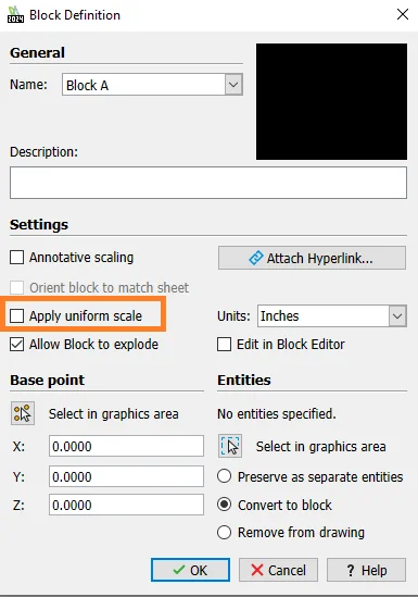
- In Block Definition window, name a block and select all the desired options.
- Uncheck option ‘Apply Uniform Scale’. Refer below image for more details.
When a block is created with option ‘Apply uniform scale’, you get option to specify different scale while inserting the block as below:
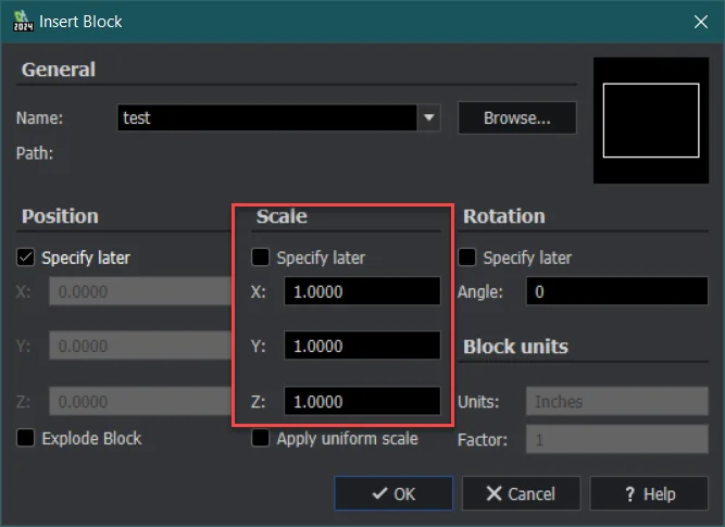
If you select ‘Specify later’, you can change block scale after inserting it using Properties windows as explained in next point.
- Type ‘PROPERTIES’ in command window to display Properties palette. When you select a Block, its properties will be displayed. In Geometry section, change the fields for Scale X, Scale Y and Scale Z to the values as per your requirement:
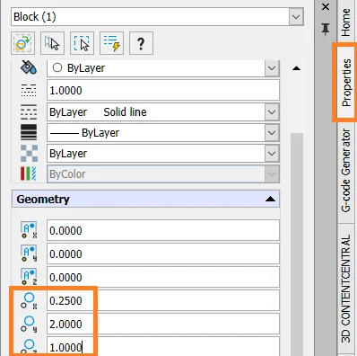
- The block will automatically update to the scale factors that have been specified. You can Explode the block for separating the entities.
2. Understanding Motion Along a Path with Path Mate
– by Kundlik GADADE
The Path Mate feature in SOLIDWORKS® is employed to restrict a chosen point on a component to follow a specified path. This capability enables users to define the path of a specific point while also providing options to select the pitch, yaw, and roll of the component as it travels along the designated path.
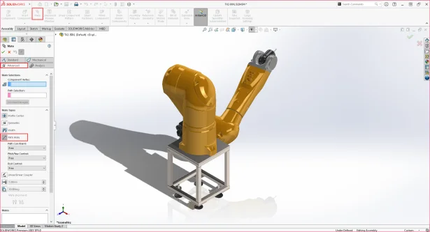
In the presented example below, a 6-Axis robot obtained from PartSupply is used. The robot is configured with all the necessary mates to allow its movement, and a vertex is strategically added at the tip to enable motion along the designated path. Additionally, the path is created using a sketch.
To create a Path Mate:
- Navigate to the Assembly tab and click on Mate.
- In the PropertyManager, go to the Advanced tab and select Path Mate.
- In Mate Selection:
-
- Define the Component Vertex to attach to the path.
- For Path Selection, select the contiguous curves, edges, or sketch entities. In the illustrated example, a sketch is utilized as the path for the Mate.
-
- Under Mate Type, choose a Path Constraint. In this instance, the Free option is selected, allowing the component to be freely moved along the path.
- Set Pitch/Yaw and Roll to Free to avoid constraining the component under the respective controls.
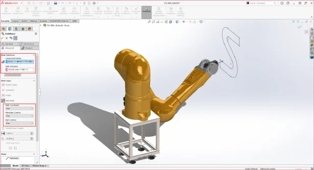
- Upon completing the selections, click Ok to apply the Path Mate. Subsequently, you can test the movement by dragging the component along the defined path.
The Path Mate feature extends its utility to Motion Analysis for creating a Path Motor, enabling controlled motion along a designated path:
- Create a Motion Analysis study and click on Motor.
- Choose Path Mate Motor as the Motor Type.
- Under Mate/Direction, select a Path Mate from the FeatureManager Design Tree.
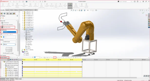
- Define motion parameters under Motion, specifying displacement, velocity, or acceleration values as the body moves along the path.
- Confirm by clicking Ok to add the Path Motor.
To trace the path in Motion Analysis:
- Click Results and Plots from the Motion Analysis study.
- Under Result, select Displacement/Velocity/Acceleration for the Category.
- Choose Trace Path for the Subcategory.
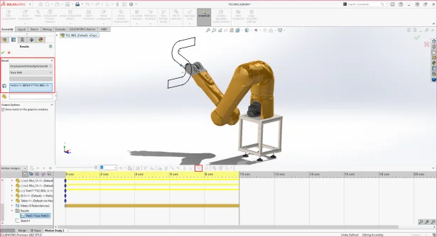
- Select a Vertex on the assembly.
- Enable the “Show vector in graphics window” option and click Ok.
- Execute the Motion Study by calculating and playing to observe the motion of the designated point along the defined path.

3. One Minute Tip – Why does component rotates in a certain direction when I open a sketch on a face?
-by Mario IOCCO