

Hello to all,
Welcome to the new edition of the SOLIDWORKS® Support Monthly News! This monthly news blog is co-authored by members of the SOLIDWORKS® Technical Support teams worldwide. Here is the list of topics covered in this month’s Blog :
Understanding the Axis Systems in SOLIDWORKS® and 3DEXPERIENCE platform.How is the time for ‘End Cutting’ calculated in SOLIDWORKS® Costing ?Why does SOLIDWORKS® Freeze or Crash when loading Toolbox add-in?
1. Understanding Axis Systems in SOLIDWORKS® and 3DEXPERIENCE platform
– Kundlik GADADE
In today’s cloud-based design landscape, applications like xDesign and xShape offer a wide range of capabilities to designers. SOLIDWORKS® users can easily find similarities between these apps and the familiar SOLIDWORKS® software. However, it’s crucial to understand the differences that exist between these platforms. One common difference that most users notice is the change in orientation, when importing parts created in SOLIDWORKS® or xApps. This means that a part created in xApps might not have the same orientation when exported and opened in SOLIDWORKS®.
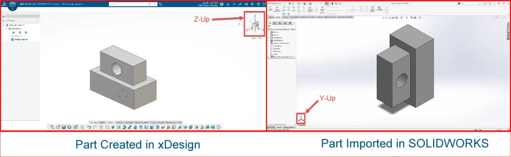
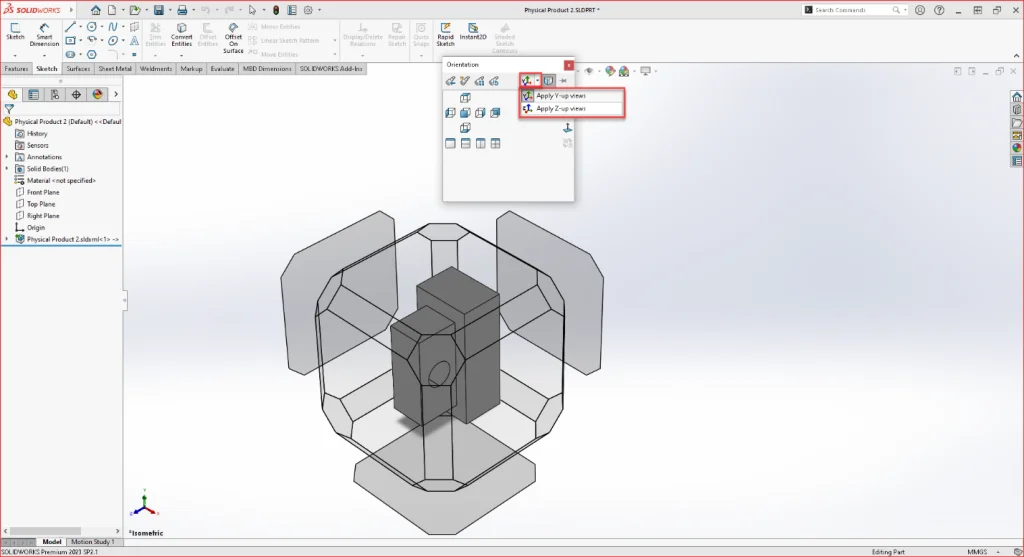
To comprehend this behavior, let’s delve into the fundamental axis systems of both environments. In SOLIDWORKS®, you may have noticed the axis triad within its interface. In the standard orientation, the triad displays the Y-axis as Up. On the other hand, xApps follows a Z-up axis orientation (visible in the top right corner). This discrepancy is often the reason for changes in component orientation when transitioning between tools. Fortunately, there are several methods to address this behavior while working in SOLIDWORKS®.
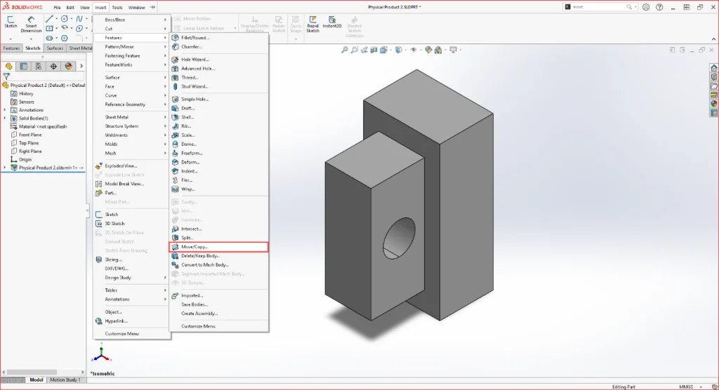
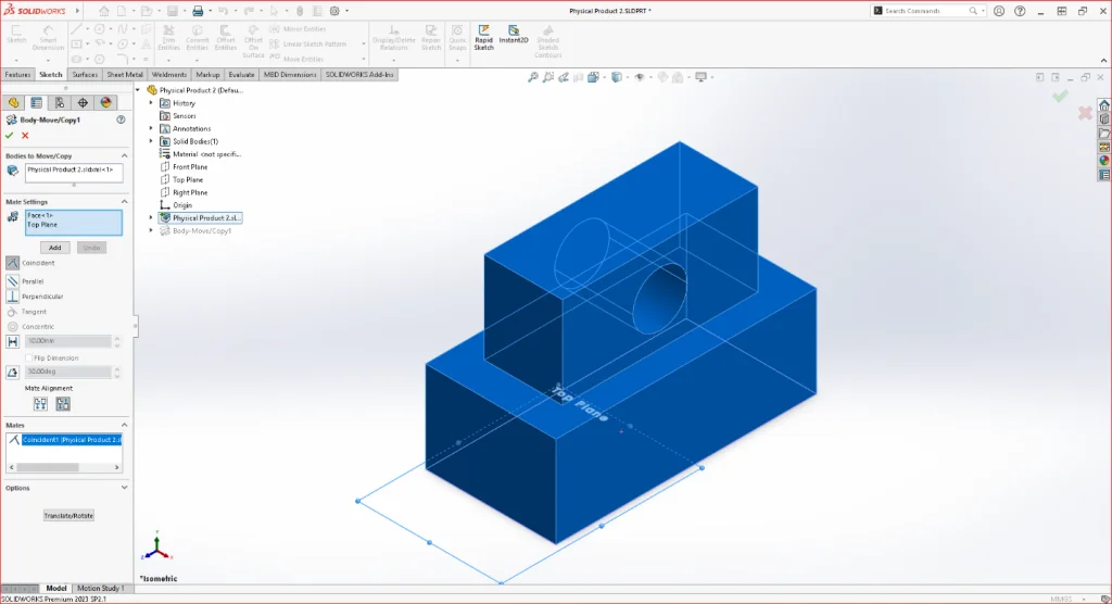
- Move/Copy Feature: You can utilize the Move/Copy feature to change the orientation of a component in SOLIDWORKS®. To do this, go to the Insert tab, select Features, and then choose Move/Copy. This feature provides options to select the bodies you want to orient and the mating option to move them into the desired orientation.
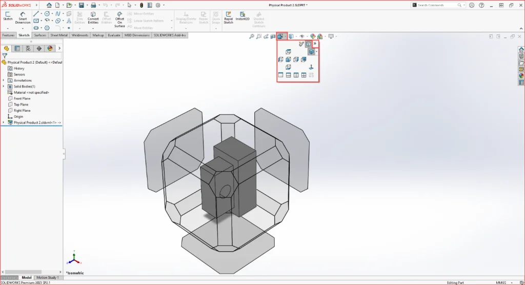
- Up Axis Flyout Feature: Another straightforward option is to change the orientation. To do this, navigate to the heads-up view toolbar and select View Orientation. Alternatively, you can press the spacebar to access the View Orientation Toolbar directly. Within the menu, you’ll find the Up-axis flyout selection. Clicking on the dropdown will provide you with options for view selection, which will be set to Y-Up by default. You can change it to Z-Up to align with xApps, and a pop-up will appear to confirm the changes. Click “Yes,” and your orientation will be modified.
Note:
- When we import SOLIDWORKS® file into xApps, it opens the file in Y-Up orientation. However, that model may not be in the same orientation if we insert it into any assembly on 3DEXPERIENCE platform.
- It’s important to note that any changes made to the component’s orientation will be reflected in the already saved drawings. Therefore, exercise caution when applying these changes to existing components.
By employing these methods, SOLIDWORKS® users can effectively manage the orientation differences when working with 3DEXPERIENCE apps, ensuring a smoother transition and consistent alignment between different design tools.
2. How is the time for ‘End Cutting’ calculated in SOLIDWORKS® Costing ?
– By Daniela KOLOSZKO
While calculating ‘cutting speed’ for end cut operation, SOLIDWORKS® takes into consideration the surface area of the face being cut. The calculation is done by following these expressions:
- End cut cost = time required for operation x (machine cost + labor cost);
- Time required for the operation = face width / (surface speed x multiplier rate);
- Surface speed value comes from machining template > End cut operation tab > Meters per minute column.
- To determine ‘multiplier rate’, we take into consideration face area, face width, and tooth pitch.
- Average cut width = face area / face width.
- Based on ‘average cut width’ value , best suitable tooth pitch is selected.
- This tooth pitch value is compared with the standard tooth pitch values to get a multiplier rate. These values are hardcoded i.e. directly used for calculation.
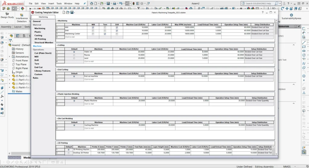
For example, to calculate Plate cutting, we use the following workflow:
- In the template, ‘Plate thickness’ is defined in the Machining tab.
- In Machine tab, the Cutting machine parameters are defined.
- Time per cut length for particular thickness is defined in the Cut(Plate Stock) tab
- SOLIDWORKS® calculates the perimeter of the larger face and calculates the time by using the parameters defined in Cut(Plate Stock) tab.
3. Why does SOLIDWORKS® Freeze or Crash when loading Toolbox add-in?
– By Deepika PUJARI
Loading the Toolbox Add-in, displays following warning message: “You appear to have experienced problems the last time you loaded the C:Program FilesSOLIDWORKS CorpSOLIDWOKRS\Toolbox\SwBrowser.dll add-in.”
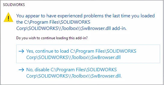
- Click ‘Yes, continue to load C:Program FilesSOLIDWORKS CorpSOLIDWOKRS\Toolbox\SwBrowser.dll’ SOLIDWORKS will crash shortly after attempting to load the Toolbox.
- Click ‘No, disable C:Program FilesSOLIDWORKS CorpSOLIDWOKRS\Toolbox\SwBrowser.dll’ SOLIDWORKS will continue working but the Toolbox will not load.
To resolve this, try below steps:
- Exit the SOLIDWORKS® application.
- Open the following folder location: C:Users
AppDataRoamingSOLIDWORKSSOLIDWORKS 20xxToolboxdata 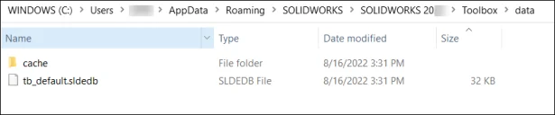
- Make a backup copy of the ‘tb_default.sldedb’ file by renaming the copy to something like ‘tb_default.sldedb.BAK’.
- Delete the original version of the ‘tb_default.sldedb’ file.
- Relaunch SOLIDWORKS application. SOLIDWORKS automatically recreates the ‘tb_default.sldedb’ file. [OR – Try copying the ‘tb_default.sldedb’ file from a working machine to problematic machine].
- Enable Toolbox add-in, the add-in should load without issue.
If you continue to face the issue, please contact your Value Added Reseller.